REBUILDING
THE MORGAN FRONT SUSPENSION
by Lorne Goldman revisted September
22, 2011
SOME DEFINITIONS
Wheel Spindle or Stub
axle: the front axle component to which the front wheel, brake caliper
and rotor, shocks and road springs attach. Slides up & down on the
kingpin. One per front wheel.
Brake Caliper: on
cars with front wheel disk brakes, the clamshell shaped component housing
the brake pads, to which the brake line attaches. Bolts to the back
of the wheel spindle. One per front wheel. (Replaces front
brake drum technology on older models)
Brake rotor: again
on cars with front wheel disk brakes, the round flat plate like device
which turns with the front wheels. Secured to the wheel spindle by the
wheel bearings. Straddled by the brake caliper, with a brake pad
residing on either side of it at approximately 2:00 o'clock. One
per front wheel.
Track Rod: the rod
connecting the left wheel spindle to the right spindle, and also the steering
arm from the steering box. Each end terminates in a ball joint, which will
need to be separated where it attaches to the wheel spindle.
There are VERY few jobs on
a Morgan that present a danger to the operator. Of course, as with anything
on a car, there is always the possibility of damaging a component or getting
the job wrong but few Morgan tasks present a personal danger to the home
mechanic who takes standard safety precautions. The Morgan front end disassembly
and assembly is an exception to this. There are dangers. Yet it draws amateurs
as this task, specific to traditional Morgans only, has become an icon of what the
accomplished home mechanic can do. An Everest to climb.
Recently, a Morgan internet
forum publicly posted how-to instructions prepared by a new owner who attempted
the job without advice or research. Sadly, aside from technical errors
that will require the job to be redone, his method is inherently dangerous
and caused concern amongst those who have done this job before. Word arrived
to me from France last week that a mogger had been very badly hurt following
his instructions. Please beware!
GoMoG has had a spotless record
for 28 years. We used to provided three (3) methods here to do the job,
depending on the reader's skill level and experience with a Morgan front
end. There has NEVER been a come-back or mishap on any of them in all that
time. However, I have decided to remove the more expert methods and concentrate
on the one I consider the safest. It has been used with uneventful success by hundreds of first-timers for
a decade. I have
made these instructions as detailed as possible. If you have questions
or comments. Please contact me through https://gomoggarage.space/index.php
READ THE SAFETY NOTES
FIRST. The ignorance of one of these elements in the other instructions
caused the accident referred to above.
SAFETY
COMMENTS AND WATCHPOINTS
PRIORITY. The bottom line to this job (which becomes super simple after 5-10 times) is safety. But someone at home, if they use the right components, will only have to do this job once on
their car. There are aftermarket components and maintenance,
popularized by eMog, that can make a Morgan front suspension last a
life time. The issue is that the spring pressures involved are
enough to cause great damage to anything adjacent and one of those
things adjacent is YOU. The detail I employ here is a function of that
caution. This method is not the fastest one, it is merely the safest
one.
1. When working on the front
suspension,
the cross-axle must be seated on jack stands or their equals. Don't work
on the car with it resting on a jack only.
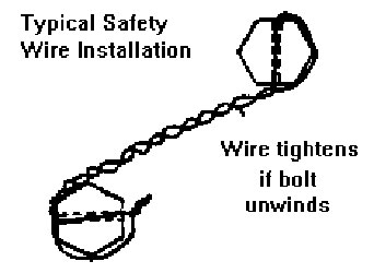 2. Make sure the caliper
securing bolts have been safety wired such that the wire will tend to tighten
the bolts (see sketch).
2. Make sure the caliper
securing bolts have been safety wired such that the wire will tend to tighten
the bolts (see sketch).
3. After the job, check every
nut and bolt again after you have put about 100 miles on the car. Also
check for wheel bearing play and take up if required.
4. Make sure you have all
the parts of the assemblies in the order so that you do NOT forget something
and be forced to deassemble again.
5. ASSURE that the hubs have
not been reversed. Look at each knock-off and make sure it threads in the
same direction as the rear wheel on the same side. If you have removed
the hubs, and install them in the reversed direction (threads going the
wrong way), you will loose a wheel. It is no fun --- so check!
6. Be sure to bleed
the brakes if the pipes have been disconnected.
7. Make sure you understand
which front system you have. From 2000 on, the MMC has been changing the
front and you must be aware of the changes to do the job right. Check with
the greasing
methods in this Manual to ascertain the necessary watchpoints for
each or contact the webmaster.
|
Pros
and old timers have all learned to shun
spring compressors to assist in this task. Yet recently, a first timer
installer, considered a guru on one anglo-Morgan forum, published
a how-to method that relied on them. The queries to GoMoG about
it precipitates this note. Because of the (obscured) presence of the
kingpin dust protector inside the main spring, NO pre-made compressor
can
be made to hold with any confidence. The clamp sections of a compressor
do NOT have sufficient space to seat
properly. But unknown to the enterprising first timer, who sadly never
asks advice of anyone, a store bought spring compresor only
precariously holds the Morgan main springs
inadequately until, at high tension, they can slip, allowing the spring
to expand suddenly
with enough power to kill or cause great damage. SO NEVER USE A SPRING COMPRESSOR. I
can report to you that a mogger in France who followed the bad advice,
crushed his jaw and eye socket, losing 6 teeth as well. HE
asked me to post this warning.There are others. PLEASE do not listen to people who tell you that the compression force of a Morgan front main spring is negligible.
Plus 8s anfd Plus 4s were 140ftlbs/inch for the main spring and double
that for the rebounds and if you compress them..that increases their
force.
 There are also excellent copies of the GoMoG
method for amateurs on the internet. This one is
very good. http://morganrebuild.co.uk/SusRebuild.html
(sadly the writer is less-than-perfect in other areas and has (so far)
been unresponsive to contacts). Lovely diagrams for old Morgans!) Please, my fellow owner, be wary of
anything you hear on some forums. In fact, please beware of everything
you hear, period! There are also excellent copies of the GoMoG
method for amateurs on the internet. This one is
very good. http://morganrebuild.co.uk/SusRebuild.html
(sadly the writer is less-than-perfect in other areas and has (so far)
been unresponsive to contacts). Lovely diagrams for old Morgans!) Please, my fellow owner, be wary of
anything you hear on some forums. In fact, please beware of everything
you hear, period!
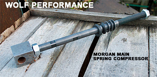
UPDATE 2020
The quintessimal pros, with more than their fair share of such work, and
extensive metal work abilities, occasionally fasion their own (safe!) proper spring compressors for Morgans. Cain Poulton (aka Wolf
Performance) also sells his to dealers and (plush) enthusiasts at a VERY reasonable price. If one is looking for safe shortcuts..this is what to buy. I am thinking of buying one myself as it makes front end experimentation very easy.
|
PARTS
NEEDED
1. Two hardchrome kingpins (avoid the MMC stainless)
2. Two new main springs
3. Two rebound springs.
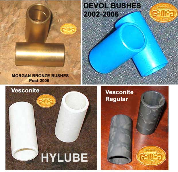
4. Four bronze bushes. (See
bush types) (The new ones have a grease groove cut in them and should
only be pressed in one way which is more or less obvious in examining them.)
5. Two new damper plates.
(The damper blades and shims can be changed at any time but now is as good any.)
6.
You should change
the main spring top bolts, (I do not advise the use of a oiler
bolt and the lock nuts below. Use a graded top bolt. These parts, even
more than head bolts, or axle u-bolts, stretch and weaken with usage.
7. You will need wire to
re-wire the brake caliper bolts.
8. Pack the assemblies with bearing grease.
TOOLS
NEEDED
1. Rubber gloves (if
wanted)
2. Small trolley jack
(borrow one if need be)
3. Spanners, 21 mm,
14 mm, 13 mm, 11 mm,
4. Spanners, ¾
in., 9/16 in, 7/16" and 1/2"
5. 11/16 in socket
6. At least one if
not two ratcheting 1/2" (or 13mm) spanners. The job is a pain without one.
7. Small handheld sledge
hammer
8. Lead knockoff hammer
9. Two needlenose
pliers
10. Jackstands and/or blocks
11. 2 wire coat hangers or
empty boxes
12. 12 inch pry bar (flat
type used by burglars, available at any hardware store)
13. You may need a tie rod
end remover.
14. A cut down Phillips screw
driver.
15. Two lengths of 1/4 inch-
20 threaded rod approximately 4.5 to 5.0 inches long. (Cut the rods with
a nut already on. Then slowly thread it over the newly cut ends to repair
the threads and make sure it is easy to put the nuts on.)
16. A MORGAN spring compressor or none at all. I have never used a spring compressor
l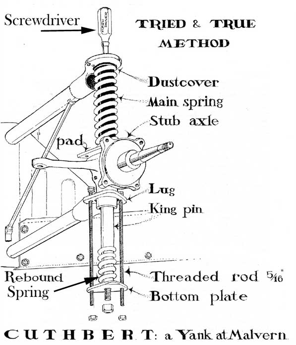
STEP BY STEP - DISASSEMBLY
&
ASSEMBLY
1. Clean your front suspension.
Use a high pressure hose or brake spray cleaner. The front end can become
unbelievably greasy due to oil from the one-shot lube, grease and road
dirt. It builds up. This is a much easier job for those who keep their
front end cleaned.
2. Jack up the front of the
car and place it on stands. You will need about 18" of height.
3. Remove the spinners
and wheels.
4. Have little boxes or hangers
at the ready and remove the calipers by cutting their lock wire, removing
it, and then undoing the caliper bolts. Slip the caliper off the rotor
and place it on the little box with the brake line still attached or hang
it under the wing with the wire coat hangers.
5. Remove the dampers from
their bottom posts only.
6. Detach the tie-rod
ends. I do so by removing the nuts and then a sharp whack or two at the cast joint
itself and it falls off.
|
Some of you may require a tie-rod end puller. Leave the nut on loosely. With the Snap-on, slip the
puller "C" disk between the rubber seal and spindle arm and install the
puller. Screw bolt end of puller onto the rod end bolt. Things will separate
with a loud snap.
|
7. Remove the damper blades
(if you have any) by unscrewing them from the spacers at the chassis and damper plate.
8.
Now... see the two little
fittings at the bottom plate on either side of the larger nyloc nut in
the middle? (At the bottom of the diagram above.) Remove ONE of these
little bolts and replace it with the threaded
rod (1/4 inch-20 cut to approximayely 4 to 5 inches long) with 2 nuts
locked at the top and one at the bottom, snuggled up against
the bottom of the plate. Then do the same with the other little
fitting.
Push the strut attached to the rear fitting to the side. No need to
remove
it from the chassis side.
| WATCHPOINT: When
cutting a threaded rod, (with a hack saw or an angle grinder ), you
will often damage the thread. By putting on a nut first, you can repair
the damage by spraying the end with a bit of penetrating lubricant and
threading off the nut. |
9. Now go to the top of
the assembly. If you have and are still using the old one-shot
oiler, detach it. This is a delicate operation as the brass coupling
which screws into the top of the large bolt holding the top of the kingpin
in place rounds off very easily with usage. Use lots of penetrating oil before
hand, and unscrew it carefully. Taking care not to bend the copper oil
tube, gently push the assembly to the side once it is removed.
| NOTE: In
2002, When the MMC switched to stainless kingpins they also changed the
thread and the top bolt to 1/2" unf. I recommend you have choose the better hardchromes which you can merely buy from any savvy dealer. |
10. Take a small screwdrivers (Phillips heads) and see if you can get them into the top hole when the big
bolt is removed from it. I use a medium size Phillips screw driver and cut off
part of the handle to make it fit. The point of this is that 3 inches or
so of the
little screwdriver, when placed down the top bolt hole, will
actually hold the assembly together without you holding it and
will allow you
to pivot the assembly to straighten it, and important factor. The
danger is loosing control of the of the kingpin and spring during
assembly or disassembly.
11. Now, while making sure the rods
do NOT pivot (I put my vice grips on the bottom of the rods and hold that to stop the pivoting) I ratchet
down the nuts at the bottom of these rods, and go from one to the other to keep them evenish and the kingpin will start to drop
SLOWWWLLLLLYYYY. Keep a hammer nearby to make the main spring stay
in place if needed.
12. When you have about 3
inches between the now dropped bottom plate and the lower frame it was
bolted to..the assembly will become looseish. Keep ratcheting down until you see little
or no tension at the little nuts you are turning on the threaded rods.
13. At this point, I take
something I have around (I used a deflated folded swimming pool raft).
and place it above the kingpin assembly to cushion any impact. I remove the little screwdriver and knock
the kingpin and spring off the top. Don't worry TOO much about it hitting the inside
of the front fender when extended– its rest position is only 2 inches (approx.)
longer than its length when compressed.
(BTW, the kingpin is not only held by the bolts.There is a little 1 inch
diameter détente in its upper frame spot that the kingpin fits into.)
14. Remove the threaded rods
by removing their top nuts. Remove the assembly by lifting it up. You can
also slip the kingpin out.
| NOTE: At this point
some people remove the rotors. This makes the other work easier but it
is more work and not strictly necessary. (See Bearing
and Rotor Removal) |
| NOTE: You can leave
the hubs in place if you have a Devol bush car. The ones with the resultant
fit blue nylon bushes as the bushes are that easy to fit. Drive them out
with a socket and extension and bang the new ones in with a a hammer and
a flat piece of wood. Once in, the fit should be fine without any reaming
or other adjustment. |
| NOTE: Have a beer. You deserve
one. |
REMOVAL
AND REPLACEMENT OF THE NEW FOR OLD BUSHES
i. After degriming
my friend's stub axles, I went to one of the machine shops in the village
and used their hydraulic press. With the help of some blocks of wood, I
got the tube in position and pressed out both bushes from one side. (This can also be done at home with a poor-man's drift. Nonetheless,
I advise the first timers to find a machine shop to do this task!
ii. Then I pressed the four
bushes in separately, taking care to get them oriented properly so that
the bush "lip" is facing outward..(bottom at the bottom and top and at
the top).
Mating New Bushings to the
Kingpins (updated 2014)
by Lorne Goldman
Morgan stub axles are not consistent. In welding the kingpin
tubes to the axles, they warp the tube. And, save for the Devol bushed
cars made between late 2001 and 2006. (scroll down for more information
under Devol), Morgan does not address the anolmalies they create by this
welding. This would require honing or reaming the tubes themselves to a
common ID and alignment of both ends. Without a common ID and alignment,
resultant fit bushes are not possible. One cannot simply press the bushes
in and expect, automatically, a correct clearance and/or alignment. In
layman's terms, without aligning the bushes at each end, you can have one
bush askew one way and the other end askew another way, making the kingpins
bind and sieze, regardless of whether their individual clearance to the
kingpin is correct. So properly mating new bushings to the kingpins is
absolutely key to the success of the job. Once the old bushings have been
removed and the new ones forced in, they will have to be mated (aligning
the bushes with each other and the kingpins and also machined so that the
interior diameter of the bushes has the right clearance for the kingpins).
This will require either that you purchase some special tools a line reamer)
or find a machine shop that will do the work with more sophisticated equipment.
I once had mine done at a machine shop with a laser-guided Sunnen honer
for about $20 per axle. I admit to using a line reamer since....more
convenient.
There are two methods of obtaining this fit. One is to
use a line reamer, the other is to have them honed. The consensus of opinion
is that the honing is preferred as a better and a computer-consistent precision
fit can be attained every time. I have not noticed a difference.
As well, honing allows for improved lubrication of the bushes on the same
principle that encourages the honing of engine cylinder walls. Knowledgeable
owners simply use hardchromed kingpins and forget such niceties.
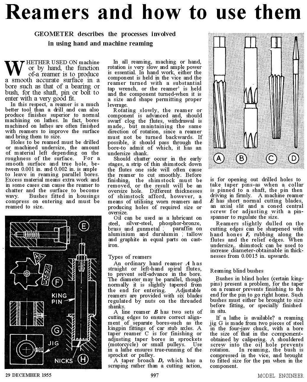
REAMING THE BUSHES
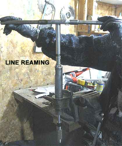
This is my wife Audrey showing how easy
it is. She was able to ream her first set of Morgan bushes
from these
instructions without my assistance. |
| DEVOL
cars only, you need not go through this process. Their blue bushes
are a resultant fit and VERY easy to press out and install without causing
damage. Drive the old ones out with a socket and extension and bang the
new ones in with a light hammer and a flat piece of wood. Once in, the
fit should be fine without any reaming or other adjustment. |
NOTE: With other,
bronze
bushes This part of the job requires specialized equipment. It can
be left to your local machine shop if you wish. The job can be done with
a reamer (it has been done this way for 100 years) but for precision a
Sunnen laser guided honer is technologically perfect..merely unnecessary. Here are instuctions for DIYers like
me.
I am looking for a line reamer source at a reasonable price. At the
moment, one suitable for a Morgan is in the range of £150. I
think they can be had for $35 USD. When successful, I will post an
advisory to the GoMoG New Additions Page. June 2020 |
|
 |
A. Then I went home and fit
the axles to be held by a large table vice (the best garage friend of the
home mechanic).
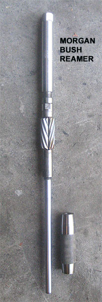
B. I then took the Morgan
line reamer Norm Patterson lent me 27 years ago. (wry smile) This is a
1" reamer with an attached rod and a removable tapered end that slides
on the rod and fits into the other end of the stub axle tube. The rod and
taper aligns the reamer and therefore guarantees that your bushes will
also be aligned with each other. That is key. You then adjust and turn
gently through each bush until the kingpin can just slide through snugly.
Don't worry too much about measuring the clearance. Feel is better than
measurements here. I greased the bushes by filling the spiral bush grooves
with my finger. Frankly, in most cases the reamer, once it has done a Morgan once, need not be adjusted at all.
C.
I increase the reamer OD until the kingpin will JUST slide in the bush
(4-5 thous clearance or 0.1020mm) with no effort. The
check is done by putting light oil (vaseline for instance) on the
kingpin. Insert it in the tube all the way, put the palm of the hand
at the far end of the slider and pull the kingpin, if the vacuum thus
created
sucks the kingpin back, good enough for me, job done. White lithium or
molybdenum sulphide (water repellants and low friction) give excellent
results as front end grease.
BUSHING REMOVAL
Removal requires a bushing
tool (see sketch) that will push out the bushings and clear the ID of the
spindle. Use a jack stand to hold the spindle, and a drift (rich man's
or poor man's) to drive out the bushing. A brass knock off hammer is about
the right weight. Both bushings are driven out from the same side.
Here
is an alternate method from Downunder.
BUSHING INSTALLATION
Installation is best done
using a hydraulic press (any machine shops and many garages can do this).
In a pinch you can, with care, use the poor man's drift and drive them
in. Here
is an alternate method from Downunder.
ASSEMBLY
OF THE FRONT SUSPENSION
DO NOT forget parts
and the order they go on! You need the little plate that attaches to the
kingpin bottom, the kingpin, the rebound spring, the stub axle, the damper
plate (or bearing thingie if you are using one), the dust cover and the
main spring.
A. Remove the little plates
from the old kingpins and fit them on the new kingpins. In case you forget,
the sloped edge of the plate is on the bottom and outboard.
B. Gather the parts needed
in the right order. Place the correct stub axle assembly (right and left
stub axles are different) on top of the opening on the lower arm of the
crosshead and then slide the kingpin into the stub axle tube from the bottom.
(This is the point were many people add gaiters or steering
bearing thingies or O-
Rings.)
| WATCHPOINT: Do not
forget the damper plate! And do not forget to place the dust cover inside
the top of the main spring before you slide the main spring on. |
C. Go find the threaded rods
you used to remove the assembly and set them up again, through the little plate and through their
bolt holes in the crosshead. Two nuts each (locked together) on the top and
one nut each at the bottom.
D. Tighten the lower nuts
until most of the slack is taken up but before the kingpin starts rising.
E. Now here is the hardest
part..for me at least. You will find that the main spring does not politely
slip into its place under the top of the cross frame. It won't do that
unless it is compressed.
Here is how I did it the first time (though I have fashioned a three sided
funnel to help me out since). I put a jack under the "nose" of the
stub axle. I angle a strong (3/16" thick) metal plate (about 4" x 15")
under the spot I want the top of the spring to go. The main spring top
may/will be facing outboard. I use my hammer to force the top flush with
the plate and inward. As I am doing this, I use the jack to straighten
the end of the
axle and that forces the
entire spring to straighten. You cannot do this before you start, because
you need the angle outward to give you more length to deal with the spring.
This spring will curve and then straighten as you use the jack and get
closer to the near the springs happy home.
Keep banging inward until
the plate is sandwiched between the top of the main spring and its place
under its crosshead position.
Now here is where life gets
exciting. With hammer in one hand and plate grabbed in the other, wiggle
the plate out while keeping the main spring in place by banging/positioning
it with the hammer. As you wiggle out the plate, you may find that you can
slip in your trusty cut down screwdriver. In any event, as you can slip
that screwdriver in and once in, you will be considerably safer.
F. Now start ratcheting up
the bottom threaded rod nuts. You can measure you progress (it is slow)
by seeing the space between the lower plate the kingpin is held to and
the crosshead flange which is its destination. You will need the hammer
to make sure the main spring behaves and stays aligned as you want.

WATCHPOINT: Be very
careful not to crush the dust covers with the 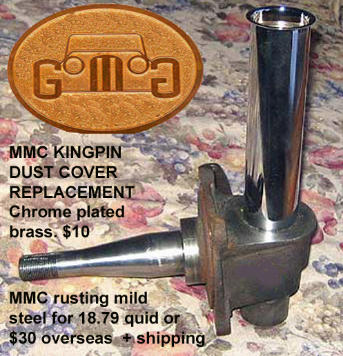 stub axle tube (it is hard
to see inside the Main spring).The dust cover fits over the tube as a very
tight fit and it is easier to crush it than not. When they approach the
point of contact, make SURE the cover slides over the tube. see
here stub axle tube (it is hard
to see inside the Main spring).The dust cover fits over the tube as a very
tight fit and it is easier to crush it than not. When they approach the
point of contact, make SURE the cover slides over the tube. see
here
NOTE: The dustcover to
the right is a plumbing extension found in any plumbing or hardware
store. The reason to switch (when convenient) is not because it is
cheaper and prettier. It is because it a much higher quality part for
the purpose it serves as it does not rust and one can see its condition
and any debris at a glance. |
G. I find that my
top kingpin
bolts cannot thread properly if the kingpins are raised fully into
their final
position. Perfect alignment of bolt and threads is unlikely when they
are that close. So I leave the kingpin about 25-35mm from the top. I
then feel for the kingpin
position with the cut down screw driver. If necessary I use a small
mirror, flashlight and hammer
to carefully center the pin under the bolt hole. Then I search for the
kingpin hole with the bolt. Finding the thread can be difficult
and could require a number of tries! (PLEASE place the cut down
screwdriver
back when you are not trying!!!!!!!!) When the center pin is under the
hole, thread the bolt (with loctite) home. It is not necessary to
tighten
it completely.
H. Once you have the bolt threaded, finish ratcheting up the nuts on the threaded rods
and then tightendown the big bolt on top.
I. Now remove one of the
threaded rods and replace with its bolt and nut. Now do the second one, Don't forget to put the strut back on.
J. Put the tie-rods back
on.
K. Fit back the calipers.
If it won't slide onto the rotor, pry the pads apart with a big screw driver
and try again. In extremis, remove the pads, fit the calipers and then
install the pads. Make sure you don't twist the brake lines. Use the wire
to lock the caliper bolts..they both have holes for that in them.
L. Fit the shocks on their
bottom posts.
M. Refit the damper
blades and spacer and attach them to the damper plates. You can allign
the plate with a few knocks of a small hammer. You can bend the damper
blades to fit them back into their slot on the frame but I usually remove
the shims and lengths of metal, clean them and reassemble after examining
them for wear. Adjust the shims (part of the damper blade assembly on the
car frame) to ensure that the assembled damper blades have no lateral motion
where they attach to the body. See HERE.
N. Install the one
shot oil pipes. (if you have them and still use them)
O. Pump the stub axles full
of grease.
P. You now need a professional
wheel alignment.
and another beer!
Q.As a word of caution, ensure
that you recheck the tightness of all fittings and bolts after your first
few kilometers, and again several times after driving longer distances
(I suggest 50, 100, and again at 200 Kms.).