 4/4
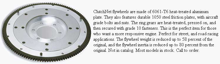
ZETEC LIGHTENED FLYWHEELS
4/4
ZETEC LIGHTENED FLYWHEELS
As you can imagine, most lightened flywheels for the Zetec
are made in the USA where the engine is the most commonly found. Check
out FocusSport or TTV
Racing or ClutchNet
Flywheels or Dunnell
Engines.

It's pretty simple, really. Take a pound or so of paraffin wax and grind it up with a cheese grater. Soak it in a half gallon of mineral spirits until all of the wax is dissolved. This might require allowing it to sit in a closed container for a couple of weeks. Stirring will cause most of the wax to dissolve, but soaking should take care of the rest. Generally try to dissolve as much wax as the mineral spirits will hold.
After that, dump in a couple of pints of mineral oil ( less of a bad smell than other oils )or a cheap non-detergent motor oil. If the mixture is thick, thin it further with more spirits or oil until it is of a sprayable consistency.
Buy one of those inexpensive cheap engine sprayers at the local auto or tool store that carries air tools. It is a metal wand with an air fitting, a spray button and a rubber tube to dip in whatever you are spraying. Rent or borrow an air compressor.
Safely elevate your car so that you can get at the underside.
Spray this solution you made onto and into every crevice, crack, hole,
and surface you can get to. Then let the excess drip off. The beauty of
it is that the stuff will soak into any spots rust can happen. It will
also bleed into the smallest cracks and folds of the body and protect there,
too. (It should be done with new cars or those which have had all rust
removed. If you repeat this carefully every year, rusting may be reduced.
| N.B. Please note that waxoyl has no impact properties, lasts for a very limited period and cannot deal with existing rust. If used over rust, it will seal in moisture and hastened the rusting process. |
WAX FILLERS
(waxoyl)
by Lorne Goldman at the eMog
Pub
As noted during our last thread on the subject, I sent out some feelers to get some hard facts on Waxoyl and the other products used for the same purpose. A happy assist here has come to us courtesy of "Practical Classics". They tested many of these cavity waxes for their UK readership in the October 2000 issue.
The Tests: The important ability of the product to fill tiny cracks and cavities. Cavity measurements were made. In this regard, they were examining the degree these waxes adhere to metal and prevent moisture entry. Bare clean metal, rusted metal were subjected to salt spray at a 45 degree angle for 500 hours (a very low testing level). The ability of the product to heal itself after inevitable scratches.
The Results:
Shrinkage Generally: many waxes are heavily cut with solvent, as the solvent evaporates the coverage shrinks and cracks exposing the surface it is supposed to protect.
PRODUCTS
Dinitrol 3125: Excellent all rounder. Panel came out as perfect as it went into the salt spray. Lost only 1 point for a tad less penetration than its rivals. Highest score. 13/14
Plastic Padding "Cavity Protect" (can liquid): Excellent performer but poor on self-healing properties. 12/14
Plastic Padding "Cavity Protect" (spray): Slight cheaper than Teroson's aerosol and a better performer. Lower score than its canned brother or Dinitrol. 11/14
Hammerite Waxoyl: Best known of the bunch. Worst
performer . 8/14. No penetration whatsoever..as soon as waxoyl hits
a cool surface it sets without seeping in. Super self-healing properties
though. No visual signs of shrinkage after the 500 hours but was the only
product where saltwater penetration was detected. By far the least expensive
of all products at 9.40GBP per 2.5 litres. However, it may be one of
the reasons why British classics have their reputation for rusting.
| N.B. Recently a new "better" version of black Waxoyl has been advertised. Remember that waxoyl melts. As long as it is a clear substance, there is no visual effect..but the black stuff will make your vehicle a mess. |
If wax filling is your protection choice, the article suggests the following;
- Do not wax-treat before painting. Wax is almost impossible to remove completely and it will play havoc with any paint applied after.
- Try and treat your car in the summer months, when there is the highest chance the cavities are dry. If not, you will be sealing IN the destructive water
- Always follow the manufacturer's instructions as to pressure and temperature.
- Unless treating brand new metal, use a degreaser and then a rust converter before using a wax coating. (See Neutra 661, Owatrol and Dinitrol RC 800)
SETTING THE TIMING ON A TR2/3/4
The TR2/3/4 is designed to have its timing set statically. Set it this way:
With the ignition OFF for safety, always turning the motor over by hand in the normal direction of rotation and position the crank at 4 degrees Before Top Dead Center (BTDC).
Use the vernier adjuster and a 12 volt test light to set the points so that they are just opening, with the light clockwise, and with thumb pressure on the rotor. Mark the crank pulley for 4 degrees BTDC (as the diameter is 5.55 in. 4 degrees = .1936 in (as in 0.2")
This is much easier and more accurate than the manual's TDC-and-fiddle instructions. Good tuners actually check that the TDC mark is accurate. If you choose file a notch in the pulley as an indication, radius the notch so that it is not a place for a crack to start.
A dwell meter and/or dynamic timing light are fine diagnostic tools for this vintage distributor, but NOT the way to set these adjustments.
ADDENDUM: In TR 2/3/4 Workshop
manual published by Scientific Publications, Sydney, (1965) it gives
the TR2/3 distributor (type: DM2P.4) cam angles (dwell) as:
Open 30° +/-
3°
Closed 60° +/- 3°
The points gap is given as 0.014
- 0.016."
TIMING YOUR TR 2, 3 & 4
Originally published in the Triumph Register
of America National Newsletter issues #95 and #96
GENERAL UNDERSTANDING
This is a look into the task of setting ignition timing
on your TR2, TR3, or TR4. The Triumph method is different from the
way timing is set for most other makes.
Timing tries to determines the exact instant that each
spark plug will fire and light the compressed fuel and air mixture in
each cylinder. This point is usually expressed as a certain number
of degrees before top dead center (BTDC).
Top Dead Center (TDC) is the point where a designated piston has completed its rise to the top of the cylinder, and the fuel/air mixture has been compressed as much as it can possibly be squeezed. Any further rotation of the crankshaft will begin to pull the piston down and away from the spark plug (and cylinder head). What wed really like to see happen is that the spark plug will fire at this exact moment, causing the fuel and air mixture to combust and expand, driving the piston down to create the power we need and the noise we love to hear. The combsution takes a fraction of a second to complete, thus the need to start the fuel burning a few degrees before the piston reaches the TDC position. The degrees that were referring to are degrees of rotation of the crankshaft, with 360 degrees being the total number of segments (degrees) that define a circle..
Ideally the full burn should be completed when the piston has moved slightly downwards, or at about 20 degrees after top dead center (ATDC). The rate of burning for the fuel/air mixture takes a set amount of time, and the time required to complete this burn is fixed and does not change. For this reason, the timing is set so that the spark plug will fire a specific number of degrees before the piston reaches top dead center (BTDC) on the compression stroke, which allows the mixture to be completely burned at the correct point ATDC. As the engine speed increases, the timing must be advanced so that the spark plug will fire a greater number of degrees BTDC, allowing the fuel/air mixture the time necessary to be fully burned at the correct point for maximum power. When working correctly, the distributor will do this automatically as engine speed changes throughout normal driving. All we must do is set the starting point, the initial timing, and the distributor should do the rest.
Our Triumph TR2-4A distributors are equipped with two separate systems for adjusting the ignition timing to meet changing requirements due to various engine speeds and throttle positions. First there are centrifugal weights inside the distributor which sense increased engine speed, and mechanically advance the timing to larger and larger numbers of degrees BTDC, giving the fuel/air mixture the time it needs to completely burn by the correct point ATDC. This mechanical advance starts working between 450 and 700 RPM and will be fully advanced, adding an extra 22 degrees BTDC, by 2400 RPM. (These figures are for a Lucas 25D4 distributor in a TR4. Other models are similar.) As engine speed slows down, the centrifugal weights dont spin as fast, and the timing retards back to a lesser number of degrees BTDC. Theres also a vacuum advance chamber on the side of the distributor which can add another 6-10 degrees of advance timing BTDC, depending on throttle position and engine load.
Now after hearing all of this, arent you glad that we only have to set the initial timing? The automatic advance mechanisms of our Triumph distributors were a great improvement over the earliest autos, which usually had a spark lever on the steering column that required the driver to continually adjust the timing as engine speeds changed. As good as weve got it, there have been many improvements since our Triumphs first rolled off the assembly line. All of this timing advance and retard stuff is now computer controlled on modern cars, and non-wearing parts inside of todays control boxes means that setting timing is now a ritual reserved for those of us afflicted with old car disease.
In days past, when setting the timing of a car was a routine procedure, a strobe light affair called a timing light was normally attached to the number 1 spark plug and the timing was adjusted while the engine was running at idle. On most cars, this procedure produced the desired results because the idle speed was lower than the engine speed where the centrifugal weights would start to advance the timing. The Triumph owner however, will not achieve the desired results when setting the timing with a timing light.
If you recall from above, the mechanical advance can begin between 450 and 700 RPM. Thats pretty slow for a TR engine to idle, and without knowing exactly where it starts advancing, and by how much, we should probably use some other method to accurately set the initial timing. Fortunately, the engineers at Standard-Triumph specified a method for setting our initial timing with the engine OFF. This is nice in that it can be done in a cool engine compartment, and it keeps fingers and tools away from spinning fan belts and fan blades.
SETTING THE TIMING
You need to know about to set the initial timing is how we know the exact moment that a spark plug is going to fire. .
It all starts with the 12-volt battery, and electricitys desire to flow from the positive battery terminal to the negative battery terminal. Even though batteries were originally installed in our Triumphs with the positive terminal connected to ground, Im going to explain this as if your car has been converted to negative ground, because it seems to make more sense (at least to me). In basic terms, electrical current flows from the positive battery terminal to the negative terminal. The engines ignition system is one of many paths that the electricity can take. The current flows from the positive battery terminal through a wire to the ignition switch, and if the switch is ON continues to the + terminal of the coil. Of course if the switch is OFF, then the current flow stops and the ignition system is disabled.
Now the coil is an interesting part, because it has the ability to turn the 12-volt electricity from the battery into the 20-30,000 volts (or more) needed to cause a spark to jump across the spark plug terminals. How does it do that? There are actually two coils (windings) of wire inside a coil, a primary coil around the outside and a separate inner or secondary coil. When electricity from the battery flows through the primary windings it produces a magnetic field, which affects the inner (secondary) windings. If the current flow (from the battery) through the primary coil windings is suddenly stopped, the magnetic field collapses, which induces a current in the secondary coil windings. The much larger number of coil windings in the secondary coil cause it to produce the high voltage necessary to jump the spark plug gap, and ignite the fuel/air mixture in your engine.
How is it that we are able to stop this flow of electricity through the primary coil windings each time that we want a spark plug to fire? Thats the job of the breaker points (usually referred to as simply points) in the distributor. In our example of a negative ground battery system, a small wire from the - side of the coil goes to the distributor and continues inside where it connects to the points. (If your car is positive ground, then the connections to the + and - terminals of the coil should be reversed.)
The points in our 4 cylinder Triumph engines are mounted inside the distributor (under the distributor cap), and they have a small rubbing block that touches a square lobe on the distributors shaft. As the distributor shaft turns, the square lobe also turns. When each of the four corners on the lobe move past the rubbing block, the electrical contact points are forced apart (open) and the flow of electricity stops. When a corner of the lobe is not pushing the points open, they touch and the electricity flows through to the engine/chassis/body (ground) and back to the negative battery terminal. By determining the exact moment that the points open and stop the current flow, we are able to know precisely when the coil will produce the powerful spark, and the spark plug will fire. This knowledge will allow us to precisely set the timing.
But before we can actually set the timing, we must be certain that the points are adjusted correctly. The points primarily stop the flow of electricity through the coils primary windings, but they are also important for allowing the current flow through the coil as well. Current must be able to flow through the primary coil windings long enough to set up the magnetic field, or the high voltage the plugs need wont be created. To assure that the points are both open and closed for adequate amounts of time, the points must be adjusted properly. This is an important first step in setting your engines timing.
To adjust your points, you will need a screwdriver (or two), and a .015 thick feeler gauge. Remove the distributor cap and rotor to gain access to the points, then rotate the engine until the rubbing block is resting on the highest point of any corner on the square lobe. To assure proper operation, we want to adjust the gap between the two contact points to be exactly .015 when they are separated the greatest amount, so its important to have the rubbing block placed on a high point of the lobe.
Begin by inspecting the mating surfaces of the two contact points. They should be flat and smooth for best results, and if they appear burned or pitted, replace with a new points set. Points adjustment starts by making certain that the ignition switch is OFF, then gently slide the feeler gauge between the two contact points to measure the gap between them. Watch to see that the feeler gauge does not force the points apart, which would indicate too narrow of a gap (less than .015). Too wide of a gap is easy to see, and the feeler gauge will be loose and able to be move from side to side. If either of these conditions indicates that the gap is something other than .015, they will need to be adjusted.
To adjust the point gap, youll have to loosen the mounting screw slightly, then move the points closer to or farther away from the cam lobe to lessen or increase the gap. Theres a slot at one end of the points where a screwdriver can be placed and twisted with one hand to move the points in and out, while you drag the feeler gauge through the gap with your other hand and feel for a slight drag. (This is easier if you leave the mounting screw just tight enough that the points will stay where you put them!) Tighten the mounting screw and re-check the gap with your feeler gauge. I often think that Lucas designed these distributors to be best serviced by three handed mechanics, because its not unusual for the points adjustment to change when you tighten the screw. If the points did move and your feeler gauge doesnt have the same slight drag as you slide it through the gap, loosen the screw and start all over again. Re-install the rotor when the points adjustment has been completed.
Once the points are correctly adjusted, youre ready to set the initial timing. There are two ways to manually change the initial timing on your distributor. One is by turning the external thumbscrew, and the other is by loosening the distributor clamp and rotating the distributor body itself. Well use a combination of both to get the correct setting.
Because well be using the external thumbscrew later in the process, its helpful to make sure it is resting in the middle of the adjustment range. Begin by turning the thumbscrew as far as it will go in either direction, then count the number of turns as you move it to the opposite stop. Divide that number in half, and return the screw to the middle of its range. Now youll have adequate adjustment in either direction should you need it later.
Weve finally reached the point where we can set the initial timing, and the next thing we must do is determine when the #1 piston is at Top Dead Center (TDC). With the gearbox in neutral, you should be able to turn the engine (clockwise when viewed from the front of the car) by hand until the timing mark on the crankshaft pulley lines up with the pointer on the engines timing cover. As long as someone has not assembled the hub and pulley incorrectly (see the factory workshop manual for more on this), the #1 and #4 pistons should both be at TDC. You can set the distributor cap loosely in place and if the rotor points to the #1 or #4 terminal locations, you can proceed with the timing adjustment. If you go past the place where the two marks line up, dont just back it up a small amount to align them. Back it up well past the correct location, and approach the spot again with a clockwise rotation of the crankshaft (to take up any possible slop due to a worn timing chain or gears inside the engine) or rotate the crankshaft another full revolution in the clockwise direction and try it again.
Now all thats needed is to position the distributor so that the points have opened just enough to stop the flow of electricity through the coil with the piston at TDC. To determine where this place is, youll need a 12-volt test light (which can be purchased inexpensively from any automotive parts or tool store or home made). Because electricity is somewhat lazy, it will always take the easiest path as it tries to return to the battery. The current will flow through the points when they are closed as opposed to flowing through a test light where it would have to do some work on the way back to the battery. When the points open however, the only option left for the electricity to get back to the battery is through the light and it immediately takes this new return path, lighting the test bulb along the way! Therefore, with the ignition switch ON, if you touch one side of your test light to the distributor side of the coil, and attach the other side to a ground, the light will come on at the very instant that the points open and the spark plug would fire. Simply loosen the clamp at the base of the distributor, and rotate the distributor until you find the spot where the light just blinks on with any movement of the distributor. Remember that the square lobe rotates counter-clockwise, so youre looking for the spot where the points will just open, not the closing point on the back side of the lobes rotation. Turn off the ignition switch, and tighten the distributor clamp. Add a tiny amount of lubrication to the rubbing block to reduce wear, and youre almost done.
Youve just set the ignition timing to fire the spark plugs when each piston has reached TDC, but Triumph has specified that this setting should actually be 4 degrees before TDC. How are we going to do this? This is the easy part. Just turn the external thumbscrew in the A direction (advance) as indicated by the arrow. There is a reference line through the middle the thumbscrew, and one complete turn is equal to 8 degrees of adjustment. Therefore, note the position of the reference line and turn the screw ½ turn in the A direction to set your ignition timing at the factory recommended 4 degrees BTDC.
Congratulations! Your timing is now set. Re-install
the distributor cap, pick up all of your tools, and take that Triumph TR
out for a drive
TR4 Overheating Issue
by Michael D. Miles
Like many TR motored Plus 4s, mine seemed to like to run very hot (needle just kissing the underside of the Hot marker on the scale) but I recently observed something.
The half-dozen times I've been out this spring the car has run well for an hour and then seems to start running rougher and hotter. It appears to have little to do with traffic but it manifests itself in rough running and sputtering under load (starting at traffic lights). Once up in the RPMs and steady, it smooths out.
Knowing that I have leaky throttle shafts got me thinking about whether it was running lean which got me poking around the SUs. I then noticed that the forward carb piston had almost no damping on the upstroke. I squirted in some damper oil (how much is enough? I simply loaded it until full stroke produced a drip out the breather hole) and drove for almost two hours without any abnormal events.
My speculation is that the forward carb may have been
running lean without the piston moving properly (under-damped) and the
extra lean running was causing the
Occasional sputter, still more heat, and low torque.
TR4 Overheating Issue II
by Fred Winterburn at the eMog
Pub April 1, 2011
Button is right that your car should not overheat at 80 degrees F.
Not all TR water pumps have the right clearance and I suspect that most have way too much end-clearance between the impeller and the pump body. This is not a very well designed impeller and could have used a shroud so that clearance was not such a big issue. Adjusting this end clearance is possible on some pumps by pulling the impeller back a bit on the shaft. The original pump in my car #3504 had a gold colour anodised aluminum impeller and this was possible, however the County brand pump I replaced it with had a cast iron impeller that wouldn't budge (even with some heat). I reduced the end clearance from 80 thou to 5-7 thou with the gasket. At 80 thou it would not pump at low speed at all. The difference was dramatic, and at high speed it pumps many times better too. With the County brand pump I needed to add a spacer inside the pump body to reduce the clearance.
TEMPERATURE TROUBLES
(Plus 4)
from Robin King's Column June 1973 FORMAT, the
newsletter of the Morgan Plus 4 Club
Normal operating temperature for your engine is about 75 C. If you are running colder, you are losing efficiency, and if it is appreciably hotter, you can get into trouble.
If your engine runs too hot consistently and overheats or boils on a slight grade or on a hot day, there are several possible causes. The first things to check are the most obvious and the easiest. First be sure there is an unobstructed flow of the air to the radiator. The central location of the fog light, as furnished on most Morgans, is a major contribution to overheating in this area (as are badges and badge bars, GoMoG Webmaster). Bc sure your radiator passages are not full of bugs and dirt. Clean then out with a hose from the back. From this, go to your water system. Start by checking the condition ot the water in your cooling system. If it is full of rust and dirt, drain and flush the system until you are sure it is clean. If it is excessively dirty, it is a good idea to have the radiator backflushed to be sure. Next, look for leaks around and under the radiator, at various hose connections and around the water pump and petcock on the engine block. When checking the hoses, be sure they are not soft when you squeeze them. A hose may look O.K. on the outside but can have a loose flap or blister on the inside restricting the water passage.
If everything is OK so far, check the fan belt to be sure it is in good condition and not slipping. The next step is to check the water pump and thermostat. Remove the radiator pressure cap and rev up the engine. If the water pump is working properly and the thermostat is not stuck closed, you will see a turbulent condition on the surface of water. If the water remains still, it is usually a bad thermostat since pump failures are relatively rare.. Remove the thermostat and repeat this test to check the pump itself.
If your engine still won't run cool., start checking the fuel mixture and check for leaks around the induction system. If your carburetors are set too lean, or are excessively dirty, they will cause hot running. Check all the joints in the manifold (intake system) by smearing a little engine oil on the joints (one at a time) and rev up the engine. If your exhaust shows blue smoke, you have a leak and should tighten the joint, or replace the gasket. (You can also check this with a can of spray ether, or "Quickstart spray" [check the label], with the car idling VERY lightly spray the joints..if the idle changes you have leak..GoMoG Webmaster).
Another common cause of overheating is retarded ignition. This can be due to poor timing or sticking of the automatic advanceretard mechanism at the base of the distributor. The vacuum advance can cause this by a leak in the diaphragm too. I have found that this retarded ignition is quite a common situation. Many mechanics will set an engine slightly retarded if the customer complains of "pink- ing". Usually it is caused by lugging the engine at too low revs.
Another contribution to a hot engine can be an oil which does not have enough viscosity index or will foam, and lose its conductivity accordingly. If you do a lot of stop and go driving, it pays to use a a premium quality multi-grade oil. If you have been using a 20 wt., use a 10-30, if you have been using a 30 wt., go to a 20-40.
If you have done all the proceeding and still have
a hot running engine, start looking for burned valves warped head, and
other major problems.
I am pulling the TR4 engine
out of my '63 plus four for some serious fun. It's all ready
to go (I think) everything is disconected but there are three studs at
the top of the bell housing that seem to be holding it to the engine and
I don't want to break anything at this point since.
Cheers, Scott
They are fixed studs, with nuts off take a wide blade
screwdriver and lightly separate the two units and then pull the engine
forward or you can "rock 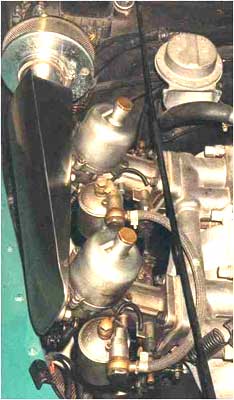 the
block" with a bit of tension on the engine pull chains and separate it
that way.
the
block" with a bit of tension on the engine pull chains and separate it
that way.
VERY IMPORTANT, you are also doing a separation
of the "long prop shaft" that connects your trans to engine. You must come
straight out until the shaft clears the back of the crankshaft and clutch
assembly or you will bend the "QUILL" which is te two inches that plugs
into the pilot bearing in the end of the crank. BE CAREFULL, as to replace
that shaft you will spend a few bigger bucks. It is hard to make straight
when bent. Go easy and take your time.....Sincerely, John H. Sheally II
The TR engined cars never came with aircleaners, no room. They can be fitted with a carb change. Your car should have the short intake manifold. If you change to a HS6 carb in place of the H6, you gain enough room for something like a Stellings & Hellings unit.
Here is a picture, from Arto Peltonen in Finland, of a '59 Plus 4 with an aftermarket aircleaner. There are listed, as well, in some Morgan Agent's catalogues.