| FOREWORD:
Morgan
steering colums have been vulnerable to oversized stomachs since the collapsible
steering column era began some decades ago. There is not much space for
girth between the bottom of the steering well and the bellies put a big
pressure on the bottom the steering wheel. In the first sorts of collapsible
columns, the collapsible wheel feature breaks. When this will happen be
a function of the size of the belly involved and the time involved. The
is no immediate danger. Howver, the steering wheel will shift backwards
and forward without an obvious cure. One can "pin" the column by driving
a metal piercing screw through the column at the correct point, but the
column will no longer be collapsible..(a big no-no for safety..allowing
one's chest to be crushed or skewered by a frontal impact). The repair
below makes the column as new again.
Later cars in the 2000s are also vulnerable
to larger stomachs but the effect seems more dangerous. The steering wheel
detachs. Here is what has been reported. http://www.talkmorgan.com/ubbthreads.php/galleries/213113/2
For the more portly enthusiasts amongst
us, a smaller 14" steering wheel can be considered (less than `14" makes
parking a chore) and/or, a Moto
Lita Offset Steering Wheel and/or a Moto Lita "shallow boss". They
will all produce more space in the area that is most key. They alos do
so in different ways so their effect is additive.
|
INSTALLATION OF ANDRÉ KOOPMANN'S
STEERING COLUMN BEARING
KIT
by Lance Lipscomb
NOTE:
The installation of this kit requires
the removal and reinstallation of your steering column. If you are
not technically competent to perform this task, do not attempt this installation.
The manufacturer/distributor can not be responsible for how the unit is
installed or how the various components are handled, and as such,
is not liable once the kit leaves his shop. Your safety is in your hands.
INTRODUCTION:
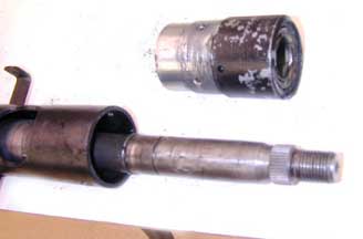
The steering column I have is a collapsible
column with a bearing at the bottom and a bearing at the top. The
bearing at the top often wears leaving a good bit of lateral movement felt
at the steering wheel. This bearing is pressed into a housing, which is
riveted into the steering column housing. The housing is designed
such that the bearing is “not replaceable” according to the Factory. However,
this kit, available from André Koopmann, a noted Morgan specialist, replaces the original housing with a machined
aluminum housing in to which you will press a new bearing. It is made solely André. It is used by Morgan Agents
and experts through the Community.
With these instructions, any machinist
or skilled home garage mechanic should be able to do the job. This installation
was performed on the steering column from a 1981 Plus 8. All collapsible
column cars remained the same until the mid-1990s.
TOOLS REQUIRED:
· Socket and open end wrenches
· Screwdrivers
· Circle clip pliers
· Arbor press ( a vise could
be used )
· Drill
· Tap
· Marker
· punch
· brass drift
PROCEDURE:
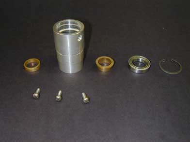
1. Check your kit to ensure that you have
all components.
·
Kit will include
· 1 Aluminum bearing housing
· 1 bearing
· 1 brass “ top hat” bushing
· 1 brass ring bushing
· 1 large circle clip
· 3 socket head machine screws
· 3 slotted head machine screws
· 3 lock washers
Note: only three screws are used to install
the kit, you are given a choice of type
|
 |
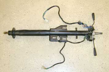
| 2. Remove the steering column from your
car and take it to a work bench for the rest of the procedure |
|
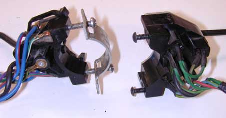
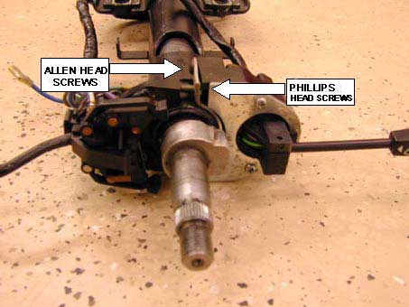
| 3. Remove the turn signal wand by removing
the socket head machine screws. |
|
4. Remove the wiper control wand by removing
the Phillips head screws.
|
 |
| 5. Remove the turn signal canceling cam
by loosening the allen screw and tapping it off the shaft carefully with
a brass drift. A liberal use of WD-40 or your favorite penetrant
may facilitate this operation.
|
 |
| 6. Remove small circle clip from
shaft at top of housing. Note: save this clip, you will need it later.
|
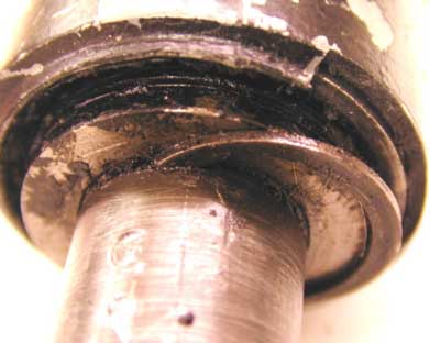 |
7. Remove shim pack from shaft.
|
 |
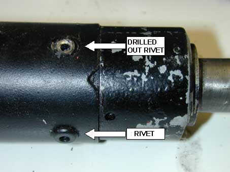
8. Drill out the three large rivets holding
the bearing housing to the steering column housing. There is a large
circular indent on the side of the housing. This locates your turn
signal lever. Mark the position of this indent on the steering column
housing.
|
 |
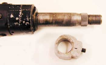
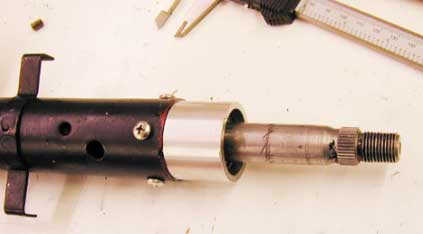
| 9. Twist and pull the housing from the
shaft.
|
 |
| 10. Clean any dirt from the
circle clip groove. |
|
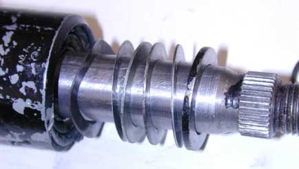
| 11. If there are any rough spots
on the shaft from the setscrew of the signal canceling cam, take a fine
file and lightly remove any raised rough spots. You will be sliding
a bearing onto this shaft and you want it smooth. |
|
12. Using an arbor press, press
the brass top hat into the bearing
|
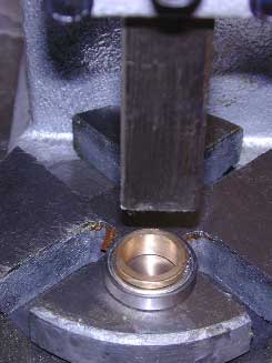 |
| 13. Using an arbor press, press
the assembled bearing and top hat into the aluminum housing. The raised
portion (brim of the top hat) goes down into the housing. Here I
am using a socket of the appropriate size to press the bearing. Ensure
that you fully seat the bearing so that the groove for the large circle
clip is exposed.
|
 |
| 14. Using circle clip pliers,
compress the large circle clip into the housing on top of the bearing.
Make sure the clip is seated in the groove
|
|
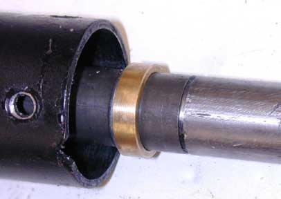
| 15. Slide the brass ring bushing
onto the shaft. It will rest against a circle clip on the shaft.
|
 |
|
16. Slide the aluminum housing
onto the shaft. Ensure that it is seated fully into the steering
column housing and the circular indent is lined up with the mark you made
on the steering column shaft earlier. The shaft is spring loaded
at the bottom of the column.
Hold the steering column upright with
the bottom on the floor, press down on the housing to ensure that the spring
on the bottom of the shaft is compressed and the aluminum housing is fully
seated in the steering column housing. *If all is correct, you should
be able to see the small circle clip groove just above the bearing in the
aluminum housing. If this is the case, use a marker to mark the screw
hole position through the three rivet holes. If this is not the case,
see the NOTE at the end of this article before proceeding.
|
|
| 17. Remove the aluminum housing
from the shaft. Center punch the spots marked for
the screws, drill and tap with the appropriate drill
and tap for the screws you
select.
|
 |
| 18. Slide
the aluminum housing
back onto the shaft and into the steering column housing. Rotate
so that the large circular indent is lined up with the mark you made
earlier. Insert the screws through the steering column housing and
into tapped holes
in the aluminum housing. Tighten screws. |
|
| 19.Press the bottom of the
shaft onto the floor to push the shaft up, insert the small circle clip
into the groove on the shaft.
|
 |
| 20. Re-install the turn signal
mechanism and the wiper motor control handle. Slide the turn signal canceling
cam into position but do not tighten the setscrew yet.
|
|
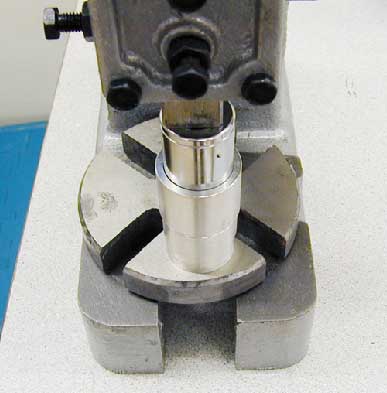
| 21.
Re-install the steering column.
Once the steering column is back in place. Ensure that the wheels
are pointed straight. Position the cam as in the picture above so
that the lobe of the cam is centered on the canceling
mechanism. Mark this position on the shaft. Turn the wheels so you
have access
to set screw. Position the cam according to your mark and tighten
the setscrew. Test to ensure the signals cancel correctly.
|
|
N.B. If all was
correct in step 16, the circle clip groove should be visible when everything
is pushed together tightly and the bottom spring is compressed.
In my case this was not so. I was
about 1 mm short of exposing the groove no matter how hard I pushed.
There are two options at this point depending
upon how your shop is equipped.
If you have a lathe, you can machine the
shoulder of the aluminum housing back the appropriate amount so that the
housing sits deeper in the steering column housing. This could also be
done at a machine shop. If you do not have a lathe, but have a bench grinder,
you can pull the steering shaft out of the bottom of the steering column
housing, mark the top of the steering column housing and using the grinder,
remove a bit so that steering column housing is shortened. I do not have
a lathe, so I used the grinder method to remove 1 mm of material from the
top of the steering column housing.
If the circle clip groove was too high
above the bearing, you can use some of the shims from the shim pack you
removed to take up the slack.
BACK