Now for the big surprise! Your car originally had
had a long and narrow wooden H shaped structure that sat on its side
and was mounted between the inner rear fender walls. A steel plate
would have been mounted on that structure and the bracket to which your
spare attaches would have mounted to the steel plate. Not any more!
The propane tank will have become part of the structure of the car.
In my car there was a ¼ aluminium plate about 16 wide and 12
high. This plate bolted to nuts welded onto the propane tank.
The plate has threaded holes to which the spare wheel mounting bracket
attaches. You will need to replace the wooden structure, as well
as the wooden boards the fuel tank will sit on. These can be made
from two pieces of ash using your table saw or radial arm saw. If
your car has the aluminium plate you will use it, but attach it to the
new wooden frame you will build.
The hardware should all be stainless steel, although the
wood screws for the spare wheel support frame can be brass. You will
need 3/8 bolts, flat washers, lock washers and nuts to secure the wooden
frame to the inner fender walls, the tank boards to the chassis, and the
tank to the tank boards. I used flat washers on both sides in each
application. You will also need ¾ long round head wood screws
and lock washers to secure the stabilizing straps to the tank boards.
The wood screws for the wooden frame must be flat head. If you do
have the ¼ aluminium plate you will need flat head bolts, flat
washers, lock washers and nuts to secure it to the wooden frame vertical
members and flat head wood screws to attach it to the lower horizontal
member. Use silicone liberally where stainless touches aluminium to prevent
or slow the electrolytic reaction will rot the alloy.
Fabricate wooden parts as needed:
Purchase two pieces of Ash a 1 x 8 x 72 piece that
can provide the two boards the fuel tank sits on (Morgan uses three boards
two the same and one thinner) and a 1 x 6 x 72 piece that can be ripped
to 1 ¾ wide pieces to build the spare wheel support frame.
I found that finished ash is not as dimensionally exact as more common
lumber. The 1 x 8 should be at least 7 1/2 wide and the 1 x 6 at
least 5 ½ wide. It will be easier to follow this section
if you have the descriptions and pictures that follow.
 All
pieces are cut out of 1 Ash. Tank boards are 35 5/8 long the
distance between the chassis rails check yours. The ends have been
dadod to ½ thick, the thickness of the original factory boards.
The dado cuts are 1 11/16 in from the ends, which leaves 32 ½
of full thickness that will sit between the frame rails check yours.
All
pieces are cut out of 1 Ash. Tank boards are 35 5/8 long the
distance between the chassis rails check yours. The ends have been
dadod to ½ thick, the thickness of the original factory boards.
The dado cuts are 1 11/16 in from the ends, which leaves 32 ½
of full thickness that will sit between the frame rails check yours. 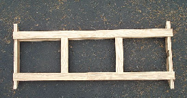
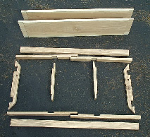
The spare wheel support frame has two pieces that run
horizontally and are glued and screwed to the under sides of the main horizontal
members. These pieces are 35 ½ long...confirm this on your
car. The main horizontal members are 19 5/8 long and have dado cuts
half their thickness and two inches wide to allow them to overlap in the
centre. There are also dado cuts half their thickness and 1 ¾
wide to accommodate the vertical members. These cuts are 11 apart,
which produces a distance between the outer edges of the vertical members
of 14 ½. The vertical members are 11 ¾ long and have
dado cuts half their thickness and 1 ¾ long at each end.
The side members are 15 7/8 long on the top edge and 11 7/8 long on the
bottom. They are notched to allow the horizontal members to fit flush
with their upper edges. The notches are cut such that the distance
between their outer edges is 11 ¾. This puts them as close
to the full width part of the member as possible. Screw holes are
pre-drilled and countersunk for 1 ½ flat-head brass wood screws.
There are two holes at each point where a horizontal member mounts to a
side member. There are also two holes where the left and right horizontal
members overlap. There is one hole where each end of the vertical
members notch into the horizontal members. There is an additional
hole 4 inboard from each of the vertical member holes. This makes
a total of eight holes that will have 1 ½ screws that go through
the horizontal members into the extra pieces that are meant to reinforce
the structure. Once the entire structure is installed additional
screws will be put in from below as near the ends of the horizontal members
as possible. The notch in the inside of the right side member is
for the radio antenna.
Rip the 1 x 8 to 7 ½ wide (if necessary) so that
the extra 1 (the bottom of the tank is 14 wide) can be used as a place
to mount the fuel filter. Then cut it into two pieces about 36 long.
Determine the exact length needed by measuring the distance between the
chassis rails above the lower flange. The original boards were only
½ thick, so dado the ends of the new boards to that thickness to
avoid having the fuel tank sit too high. Measure the width between
the chassis rail flanges to determine the width to dado the boards.
The holes where the boards attach to the frame rails and where the tank
attaches to the boards will be drilled once the boards can be put in place.
The hole that provides access to the drain plug will be cut at that time
also. Cut a 45 degree angle piece (about 1 ½) off of diagonally
opposite corners of the tank boards to permit them to be rotated into
place. At this point the tank boards are ready to be treated with
a wood preservative.
Rip the 1 x 6 into three pieces 1 ¾ wide.
One piece will yield the two solid boards that mount to the under side
of the horizontal members. They will have to fit between the side
members. Each of the other pieces will yield two horizontal members,
one vertical member and one side member. Cut the horizontal members
first and make them 20 long. You will trim them to precise length
later.
Its time to remove the spare and all the panels from
the car. You may find that there are two body-colored panels beneath
the spare. These can be detached and slipped out through the round
opening. There will be a Relief line on the propane tank, probably
flexible metal. In my car it attached to the upper coloured panel
and had a rain hat on the top. That line can be disconnected at
the end away from the tank (e.g. from the upper body coloured panel) if
necessary. Remove the bolts holding the propane fill and vent fittings
in place under the flip up fuel caps. You may find that 90° angled
pieces of sheet metal had been installed on both sides to make the rear
body panel less flexible. If so, they are bolted to the inner fender
walls and have holes through which the fuel caps are attached. The
one on the left (fill) side on my car was 1/8 thick and the one on the
right side was 1/16 thick. I decided to retain them, but notched
the corners where the horizontal wood frame members will go.
Measure the depth from the rear body panel to the removable
coloured panels mine was 1 5/8. I could see where the original
wood frame side members had attached to the inner fender walls, and determined
that the original depth would have been about ¾ greater.
I decided to split the difference to ensure that the new frame would clear
the top of the tank. The under side of the lower horizontal member
of the new frame must be about 11 ¾ above the chassis rail flanges
to clear the tank. You will need to devise ways to take some of these
measurements.
Your car may have bumper impact absorbers mine does.
They will affect the size and shape of the frame pieces (side members)
that attach to the inner fender walls. Measure the angle made by
the rear body panel and the bumper impact absorber where it attaches to
the inner fender wall. This will be the angle youll cut on the ends
of the side members of the wood frame to maximize the surface for mounting
the horizontal frame members. I cut the left side member first and
verified that it would fit as planned before cutting the right side member.
The next step was to determine where to dado the undersides of those members
so they would fit flush over the pieces of sheet metal mentioned earlier.
I held those pieces of sheet metal in place and scribed a line around their
edges on the inner fender wall. Then I held the side members in place
and marked the area to dado. I also marked the right side member
where it would have to be notched for the radio antenna.
There is a piece of wood that is part of the cars frame
and runs across the back under the top of the rear body panel. I
measured 3 5/8 down from that piece as the place to position the upper
horizontal frame member. The lower member will be mounted as low
as possible but it will be higher than the original because of the bumper
impact absorbers. That appears to produce a vertical span of about
10 between the inner edges of the upper and lower frame members.
The horizontal span between the vertical members is
fairly arbitrary at 11. That will yield an outer span of 14 ½.
The ¼ aluminium plate that supports the removable body panels is
16 wide. If your car does not have this aluminium plate you will
have to punt here. If it does, it will be mounted to the wooden frame
members with 2 countersunk flat-head bolts and two countersunk flat-head
wood screws. Before removing the propane tank reattach the aluminium
plate and measure the placement of the holes where the spare wheel support
is attached. Take measurements from bolt hole centres to inner fender
walls and to the edges of the round opening in the rear body panel.
After the new frame is installed, the aluminium plate will be positioned
and the holes drilled to attach it to the new frame.
Top bolt holes to secure the side members are the next
order of business. You will probably have to drill new holes.
The angled sheet metal pieces mentioned earlier (if you have them) must
be in place as you will be drilling through them as well. To get
the side members properly positioned I cut a 10 long by 2 3/8 wide piece
of wood to use as a template. The width of your template will depend
on the depth at which you have decided to install the new frame.
Remember that you are using the template to position the side members of
the frame and you must allow for the thickness of the bits that will mount
on the frame and under the spare. Place this piece against the inner
fender wall and up against the under side of the rear body panel.
Snug the side member up against this piece and downward against the bumper
impact absorber. This ensures that the depth is uniform top to bottom
and on both sides. Once the side members are drilled, secure them
with bolts so that you can mark the precise location of the upper horizontal
member.
Next youll need to mark the side members so that you
can cut the notches that will accept the horizontal members. I had
a piece of wood that would just rest on both side members and could just
be inserted beneath the rear body panel. I taped a small piece of
cardboard to the left side member at the top of the planned cut for the
horizontal member. I then held the horizontal test piece up against
that cardboard and measured down from the piece of frame mentioned three
paragraphs up. When I was satisfied that the test piece was properly
positioned (i.e. square to the side members) I marked the edge of the right
side member with an Exacto knife. A pencil mark might have been sufficiently
accurate. The side pieces were then removed and I marked the edge
of the left member with the knife. I then measured down from the
knife cuts to mark the position of the bottom horizontal member.
That, in turn, gave me the length of the vertical members. This may
sound sort of Mickey Mouse and you may devise a better way, but this
worked for me.
Cut the notches in the side members and sand them to fit
the horizontal members into the notches. It is a lot of detail work,
but it pays. The horizontal members are next. Dado the inner
ends (where the two pieces will overlap) to half their thickness and a
width of 2. Take them to the car, hold them in place against the
inner fender walls and measure the dimension by which the dado cuts fail
to mate. Divide this dimension in half and trim the outer ends and
recheck them in the car.
Sand the surfaces of the dado cuts and mark the positions
of the vertical members. Make the dado cuts for them and sand the
surfaces of the cuts. Recheck the length of the vertical members
(the distance between the extremes of the notches in the side members).
Cut the vertical members and make the dado cuts at the ends and sand them.
The frame pieces are almost done. Assemble the frame
pieces and drill and countersink the pilot screw holes. Be sure the
upper part of each pilot hole is large enough. Brass wood screws
are typically not threaded for their entire length. If the upper
part of the hole is too small you will twist the screw trying to drive
it in. Stainless screws would be more forgiving, but make it easier
on yourself. Treat the frame pieces with wood preservative.
PAGE 3