Remove propane hardware and
lines:
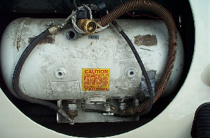 You
will probably find that the propane fuel line was routed into the passenger
area behind the right seat and then under the upholstery and up through
the scuttle. Shut the valve to the line that feeds the propane carb,
and then loosen the fuel line at the valve. There will be an escape
of pressurized propane for a few seconds. Disconnect the fuel line
from the valve. Note in the picture at right that the line has been
disconnected from the valve.
You
will probably find that the propane fuel line was routed into the passenger
area behind the right seat and then under the upholstery and up through
the scuttle. Shut the valve to the line that feeds the propane carb,
and then loosen the fuel line at the valve. There will be an escape
of pressurized propane for a few seconds. Disconnect the fuel line
from the valve. Note in the picture at right that the line has been
disconnected from the valve.
Remove the propane hardware from the engine compartment.
Note that there are coolant lines attached to one of the pieces.
Be prepared for the release of coolant. Then remove the propane tank.
Remove 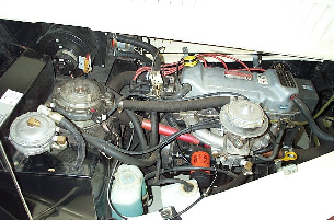 all
eight bolts that secure the tank to the steel plates and the plates to
the chassis rails and the tank just rotates forward and down. It
is rather heavy, so it helps to have a jack under it. The fuel line
can then be removed by pulling the upholstery away from the passenger side
and disconnecting the clamps. You will need to remove the right side
seat.
all
eight bolts that secure the tank to the steel plates and the plates to
the chassis rails and the tank just rotates forward and down. It
is rather heavy, so it helps to have a jack under it. The fuel line
can then be removed by pulling the upholstery away from the passenger side
and disconnecting the clamps. You will need to remove the right side
seat.
That is the easiest way to route fuel lines. The originals
went through the drive shaft tunnel. Solid fuel lines (originals were rubber)
can be bent so that they can be routed from the tank all the way up and
through new holes in the firewall. Rubber grommets are an excellent.
Short pieces of flexible tubing and clamps can be used to connect the solid
lines to the fuel filter and pump. This is safer than under the chassis
where they can be smashed or ruptured...though racers keep them outside
to make the car safer. I briefly considered routing fuel lines through
the drive shaft tunnel, until I realized that if the drive shaft broke
there the remains would be thrashing around. Another expensive alternative,
is to consider Aeroquip lines. These have all the advantages of solid lines
but are far more flexible, safer and resistant.
Install new parts:
I won't go into installation of the carburettor and air
filter, fuel pump and fuel lines. Those should be 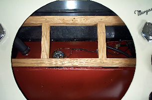 fairly
obvious. Rather Ill deal with the fuel tank and wooden bits.
Since the fuel tank will go in from the bottom, this is a good time to
install the new wooden frame. Glue and screw the horizontal
members to the side members and slip these assemblies into place and secure
with the top bolts. Glue and screw the vertical members to the horizontal
members and glue and screw the horizontal members together where they overlap.
Glue the long horizontal pieces to the undersides of the assembled frame
and drive in all screws from the top. Drill pilot holes as close
to the ends as possible from the under side of the frame and drive in screws.
Install it from the bottom and bolt it to the sides of the wooden tub with
its top bolts only allowing you to pivot it upwards a bit on these two
bolts. Admire your work. The picture at right shows the frame with
the tank in place.
fairly
obvious. Rather Ill deal with the fuel tank and wooden bits.
Since the fuel tank will go in from the bottom, this is a good time to
install the new wooden frame. Glue and screw the horizontal
members to the side members and slip these assemblies into place and secure
with the top bolts. Glue and screw the vertical members to the horizontal
members and glue and screw the horizontal members together where they overlap.
Glue the long horizontal pieces to the undersides of the assembled frame
and drive in all screws from the top. Drill pilot holes as close
to the ends as possible from the under side of the frame and drive in screws.
Install it from the bottom and bolt it to the sides of the wooden tub with
its top bolts only allowing you to pivot it upwards a bit on these two
bolts. Admire your work. The picture at right shows the frame with
the tank in place.
There is no good way I know of to mark the spots where
you must drill the tank boards to bolt them to the chassis. To bolt the
tank to the boards, you can measure with a cut out, then assemble the boards
on the floor and drill.
Lift the tank up into the opening and slide the boards
into place under the tank. This is a two-person operation unless
you strap the tank to a ceiling member and lift it over the level of the
board placement. As noted Morgan uses three boards, some with the
corners cut to allow more more lateral movement. They then can use a determined
sequence to get the boards in place easily. Remember that the securing
plates for the tank is essential to the system. The boards are sandwiched
between the tank flange and securing plates. The tank cannot simply be
screwed into the boards. It will soon become adrift and will not have any
ability to move with the flexing frame.
Make sure the boards are snug against the back of the
chassis, the tank is snug against the back of the 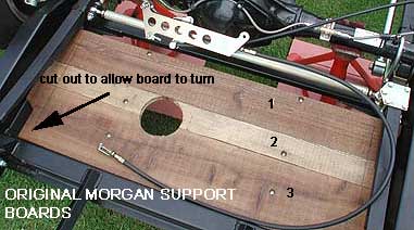 chassis
and is centred on the boards. There should be no bolts or protrusions
between the back and the tank. Drill the holes where the boards will be
bolted to the chassis. Mark the locations of the holes where the
tank will be bolted to the boards. Remove the boards and the tank
and drill the holes you have just marked through board and tank fixing
flange and under the board metal piece. Should you wish, you can use an
angle iron (alloy) to the front of the tank to further inhibit fro and
aft movement.
chassis
and is centred on the boards. There should be no bolts or protrusions
between the back and the tank. Drill the holes where the boards will be
bolted to the chassis. Mark the locations of the holes where the
tank will be bolted to the boards. Remove the boards and the tank
and drill the holes you have just marked through board and tank fixing
flange and under the board metal piece. Should you wish, you can use an
angle iron (alloy) to the front of the tank to further inhibit fro and
aft movement.
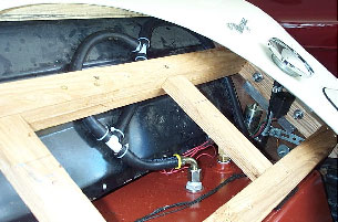
Attach fittings to the tank for fuel feed (and return
if used), and install the sender unit and rollover check valve if used.
Note from the picture above that both of these can be accessed from above
with the frame in place.
Lift the tank back up and slip the boards in under it,
making sure the boards go back in the same 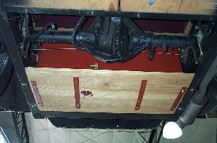 sequence
as before so the holes line up with the chassis holes. Secure the
boards and tank with stainless hardware, inserting a bolt and flat washer
from below and a flat washer, lock washer and nut from the top. Slender
arms and hands will be a big help here as there is not much room to work.
Hold a stabilizing strap up against the under side of the tank boards and
mark a screw hole location. Drill the pilot hole, making sure you
dont drill all the way through the boards and into the tank. Secure
the strap, drill the remaining holes and drive in the remaining screws.
Repeat for the other strap. The picture at right shows the tank and
boards in place and secured. The fuel outlet fitting is in the tank.
sequence
as before so the holes line up with the chassis holes. Secure the
boards and tank with stainless hardware, inserting a bolt and flat washer
from below and a flat washer, lock washer and nut from the top. Slender
arms and hands will be a big help here as there is not much room to work.
Hold a stabilizing strap up against the under side of the tank boards and
mark a screw hole location. Drill the pilot hole, making sure you
dont drill all the way through the boards and into the tank. Secure
the strap, drill the remaining holes and drive in the remaining screws.
Repeat for the other strap. The picture at right shows the tank and
boards in place and secured. The fuel outlet fitting is in the tank.
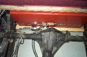 The
picture at left shows the fuel line connected to the filter and, in turn,
to the fuel outlet fitting. Short pieces of flexible hose and clamps
make the connections and the fuel line and filter are secured to the tank
boards with rubber insulated clamps. The tank had been given several
coats of shop primer and I decided to leave it that way for now.
I may eventually treat the tank and boards with waxoyl, but for now will
avoid the mess.
The
picture at left shows the fuel line connected to the filter and, in turn,
to the fuel outlet fitting. Short pieces of flexible hose and clamps
make the connections and the fuel line and filter are secured to the tank
boards with rubber insulated clamps. The tank had been given several
coats of shop primer and I decided to leave it that way for now.
I may eventually treat the tank and boards with waxoyl, but for now will
avoid the mess.
I found a rollover check valve that would provide venting
of the tank while filling. I supplied the tank 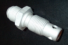 fabricator
with a nut with the proper threads and he cut a hole in the top of the
tank and welded the nut on the inside. The valve attaches to the
tank by threading into the nut. There is a nylon washer on to seal
the valve to the tank. The valve is open from bottom to top.
There is a ball bearing that is held in by a circlip. Air can escape
past the ball and out through the hoses shown. Should the car roll
over the ball bearing forms a seal against the top of the valve.
The hoses are setup so that fuel may slosh up and into the first section
of hose, and may even make it through the tee and up over the first loop.
There it will encounter a second tee and will drain back down into the
tank. The hose that goes up from the second tee loops up and back
down and out into the back of the right side wheel well.
fabricator
with a nut with the proper threads and he cut a hole in the top of the
tank and welded the nut on the inside. The valve attaches to the
tank by threading into the nut. There is a nylon washer on to seal
the valve to the tank. The valve is open from bottom to top.
There is a ball bearing that is held in by a circlip. Air can escape
past the ball and out through the hoses shown. Should the car roll
over the ball bearing forms a seal against the top of the valve.
The hoses are setup so that fuel may slosh up and into the first section
of hose, and may even make it through the tee and up over the first loop.
There it will encounter a second tee and will drain back down into the
tank. The hose that goes up from the second tee loops up and back
down and out into the back of the right side wheel well.
 All
that remains of the tank installation is to attach the fill hose to the
neck on the tank and to the neck on the fuel cap. You will have to
work with this a bit to try to minimize the kink in the fill hose.
I have found that I can usually lock the gas pump filler nozzle on while
filling the tank, but it must be positioned correctly or it will shut off
too readily. I have only once had a problem with fuel sloshing back
up out of the filler hose, and I chalked that up to operator error.
All
that remains of the tank installation is to attach the fill hose to the
neck on the tank and to the neck on the fuel cap. You will have to
work with this a bit to try to minimize the kink in the fill hose.
I have found that I can usually lock the gas pump filler nozzle on while
filling the tank, but it must be positioned correctly or it will shut off
too readily. I have only once had a problem with fuel sloshing back
up out of the filler hose, and I chalked that up to operator error.
Some Morgans have an aluminium plate that fits in the
centre of the hole with a lip that fits over the top 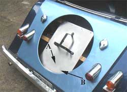 wood
member and 4 small screw into the member and held at the centre by the
three bolts holding the tripod spare wheel bracket. These bolts go through
the bracket, the plate and the wooden members. Some of us change the plate
to polished stainless, others extend the plate so they can screw it into
the wooden piece at the bottom to prevent vibration and others use a plate
large enough to cover the whole space top and bottom and side to side.
It is your option.
wood
member and 4 small screw into the member and held at the centre by the
three bolts holding the tripod spare wheel bracket. These bolts go through
the bracket, the plate and the wooden members. Some of us change the plate
to polished stainless, others extend the plate so they can screw it into
the wooden piece at the bottom to prevent vibration and others use a plate
large enough to cover the whole space top and bottom and side to side.
It is your option.
Test and adjust as necessary:
Once everything is installed you will want to check the
emissions levels. You may find that the car runs clean enough that
a cat is not needed. Emission inspection requirements in your area
will be the determining factor. In my case the carburettor could
be adjusted to burn clean enough without a cat. The other question
will be the usable capacity of the fuel tank and what the new sender and
fuel gauge show you. I took one gallon of fuel in a can and ran the
car out of fuel. I poured the one gallon in and made it to the nearest
station and filled the tank. I found the total capacity of the tank
to be 16 gallons. I then ran it until the gauge just read empty and
filled it again. I found that the gauge reads empty when 12.3 gallons
have been burned. I operate on the assumption that I have 15 gallons
and leave that one last gallon as emergency reserve. When the gauge
reads empty I have 2.7 gallons to get me to the next station. On
the highway that would yield a range of about 450 miles. Your mileage,
as the saying goes, may vary.
If using a Centroid unit, you can adjust the empty and
full readings to suit.
If you get a smell of petrol check it out. If it comes
from the vent get a small charcoal cannister from a friend and connected
the end of the vent hose to it. That'll cure the problem.