Those
(*&&!n%?/!) GENERATORS by Don Short
Once
you understand how they work, generators and regulators are not really
the monsters many people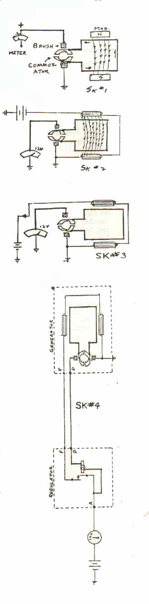 take them to be. What we would like to do here is to explain the basic
principles of generators and regulators in order to give you some idea
as to what goes on. Keep in mind some idea that the following has to do
with positive grounded electrical systems, which is like bass-ackwards
from negative grounded systems. Later, we will talk about some troubleshooting.
take them to be. What we would like to do here is to explain the basic
principles of generators and regulators in order to give you some idea
as to what goes on. Keep in mind some idea that the following has to do
with positive grounded electrical systems, which is like bass-ackwards
from negative grounded systems. Later, we will talk about some troubleshooting.
I'm
sure everyone has wondered what those letters on your regulator really
mean. Probably the most confusing aspect on your "T" series car is the
British terminology, especially where it concerns the electrical system.
For instance, "U" stands for dynamo, which to any American garage hobbyist
means a generator (or armature). "B" stands for "earth" which means ground.
"A" stands for ammeter which is not to be confused with armature. "A1"
wiring goes to the igniton switch. Mercifully, "F" stands for field and
means field.
Without
getting into a lot of electrical formula, it can be safely said that the
basic principal of a generator is that a loop of wire passing through a
magnetic field will produce a flow of electric current in that wire. Looking
at SK #1, we have our two permanent magnets, and the loop of wire rotating
between the magnetic field. The loop of wire is terminated on commutator
segments, and the output of current is picked up by a pair of brushes,
and transmitted out on the "+" wire to the meter.
If
we want to increase the flow of electric current, we can strengthen the
magnetic field through which the loop of wire is passing. This can be done
by making the field into an electromagnetic field ( SK#2). The magnets
can be wound with wire, and a battery source applied to that wire will
create an electromagnetic field. The output to the meter will be considerably
increased.
Sketch
#3 shows how the increased current flow can be controlled by removing and
reapplying the source of battery to the field coils. This can be done by
using a set of contacts, which act as an on-and-off switch. With the contacts
closed, the field coils are energized and an electromagnetic field is produced.
The field is removed when the contacts are open.
Another
type of electromagnet is a relay. A relay is nothing more than a coil of
wire around a steel core. When the coil is energized, the magnetic field
produced operates an armature, to which contacts are attached. If the current
output from our loop of wire is transmitted to the relay coil, we can open
and close the on&off contacts electrically. The relay is adjusted to
open and close at preset voltages. This opening and closing applies and
removes the battery source to the field windings, as shown in SK #4. In
addition, we can use the output from the loop to suonlement the battery
source to the field, and also to replenish or recharge the battery. The
faster the loop turns, the greater is the pressure (volts), causing more
current flow (amps). Believe it or not, SK #4 is basically it! Of course,
we really have a number of loans terminated on a number of cummtftator
segments. Looking at SK #4, we have our regulator coil preset to operate
at about 13 volts, which onen normally closed regulator contacts. When
these contacts open, no electromagnetic field is present in the generator,
consequently, no voltage or current is produced. When this happens, the
regulator coil will immediately release, closing the contacts and re-energizing
the field. This action goes on continually, opening and closing the contacts
rapidly, maintaining constant voltage in the system.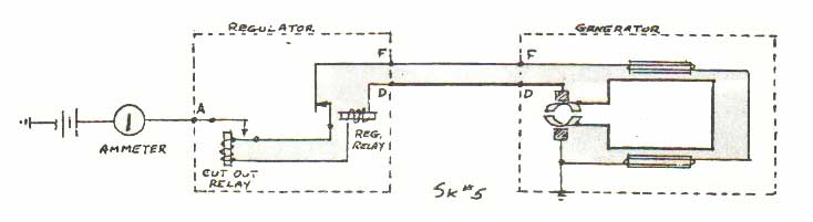
It
can also be seen in SK #4 that if our loops of wire are turning slowly,
as when the engine is idling, little or no current will be produced. The
regulator contacts will be closed, causing the battery to drain and discharge
back through the field to ground. Also, since the ammeter does not go through
the ignition switch, foe battery would drain with the engine shut down.
It is necessary then to open the battery supply from the generating system.
This is done with another set of contacts and electromagnetic coil, called
the cutout relay, placed in series with the regulator relay. The cutout
relay is also preset to operate at a given voltage, and to open when the
voltage drops to a certain level. The normal condition of the regulator
relay contacts is closed, with the engine off or idling. The normal condition
of the cutout relay contacts is open, with the engine off.
BACK