 1133 Chatmoss Dr., Va. Beach, Va. 23464; (757) 495-8229
Originally written: circa 1990
Last update:  June 8, 2009 - reformatted page & corrected email address
History
Before I get into the actual hydraulics, let me pass along a little
history of the brakes on the Morgans. The following quote identifies the
various drum brake systems that have been used.
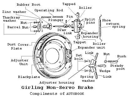 "The Morgan 4 wheeler models have always been fitted with Girling brakes.
As the car has developed more power over the years, so the braking system
has been improved to cope with the increased speed. Up to 1950 non-servo
cable and rod operated brakes were fitted, but from this time on they have
been hydraulically operated.

At the front type HLS/S (two leading shoe) units were fitted from 1950
until they were superseded by disc brakes. The rear brakes from
1950 to 1956 were type HW and these were then replaced by HL3 units".
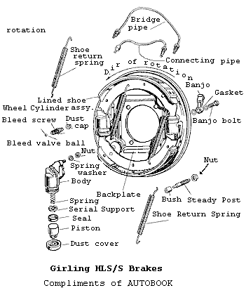 The hydraulic brake system can be broken down into three sections: the
master cylinder, the rear (drum) brakes and the front brakes. The front
brakes on a Morgan can be either drum or disk type depending on the year.
I will discuss rebuilding both the drum and disk brakes later.

Master Cylinders

The brake master cylinder on the early Morgans (pre 1968) are
"single-line system". This means that the brake fluid comes from a single
fluid reservoir into the master cylinder and is distributed to all wheels.
The problem with this system, is that if a hydraulic leak occurs anywhere
in the system, all the fluid will be drained through this leak. Thus a
complete brake failure! To prevent this, most newer cars use a "dual-line"
system. There are several configurations for this, the end result is that
only two brakes are tied together on a hydraulic line. Each pair of brakes
is fed from a separate brake fluid reservoir and master cylinder piston.
Now if a leak occurs, at least two brakes will keep working. (NOTE: There
was a great article about converting the Morgan's single-line system to the
"Dual brake system" in The Rough Rider, 89 #7 by Fred Sission.
There have been 2 master cylinders used on the Morgans, one was
fitted from about 1955 until 1959 and the other from 1959 on. Both are
similar in operation but, the early master cylinder had an integral fluid
reservoir; where as the later one used an external reservoir.

To rebuild the brake master cylinder, it must be removed from the car. (NOTE: rebuilding the clutch master cylinder is identical to rebuilding the brake master cylinder.) Start by unscrewing the brake line on the master cylinder that is going to the reservoir. Place a catch pan under the master cylinder as this will drain all the brake fluid in the fluid reservoir and some will back out of the master cylinder from the brake lines. The reason for undoing this brake line is that it is the farthest from the body and chassis since brake fluid can remove paint if it gets on any painted surfaces. While the fluid is draining, you can start disconnecting the brake pedal from the master cylinder by removing the clevis pin that attaches the brake pedal to the master cylinder. Remove the cotter pin from the clevis pin and untighten the jam (locking) nut in back of the clevis or jaw end which attaches to the brake pedal. This will allow the adjusting nut, clevis and jam nut to be unscrewed. The master cylinder is attached to a "standoff" and the chassis by 2 bolts. The lower bolt doesn't go into the chassis, only the standoff. The upper bolt goes through the standoff and the chassis. Both of these bolts must be removed. Now the master cylinder can be removed.
To disassemble the master cylinder, remove the rubber dust cover. This will reveal a circlip which can be removed using a pair of long nose pliers. To relieve the pressure on the circlip, the cylinder's rod can be pressed into the bore a little, by pressing on the pushrod with the palm of your hand. Carefully compress the circlip and remove it. Slowly release the pressure applied to the pushrod. Then it and the retaining washer can be lifted out. If there is a lot of dirt and corrosion in the bore of the cylinder, removing the piston can be very difficult. Try pressing on the piston to see if it will move. If not, spray some WD-40 into the front of the cylinder bore and into the brake line connection hole. Place the cylinder on a table, set a piece of dowel (size not critical) on the piston and gently tap the free end of the dowel to try to free the piston. To move the piston outwards, use compressed air. Be careful!! Point the open end of the master cylinder at something solid, like the back of a work bench. Adjust the regulator on the compressor to deliver about 10 psi. Cover one of the two hydraulic line connection points with your finger, and using a blowdown nozzle, blow air into the other connection port. If the piston doesn't come free, try spraying some more WD- 40 and repeating the above steps. The air pressure can be increased to about 20 psi. Again be very careful! As the air pressure is increased, the faster the piston will "SHOOT" out of the cylinder when it comes free. (Note: If you have a big enough "C" clamp, you can place it over the cylinder to keep the piston from flying out of the bore.)
Once the piston assembly is out of the master cylinder, it can be cleaned. Before starting to rebuild the piston assembly clear a space on a table and place a piece of old newspaper down. This will help you find the little pieces in the valve assembly. To rebuild the piston assembly, remove the retainer or spring thimble by gently prying its tab with a small screwdriver. Then remove the thimble, spring, and valve assembly from the piston. Next press the valve assembly towards the thimble and slide the valve stem across the key slot in the thimble and remove the valve assembly from the thimble. Finally remove the valve spacer and the spring washer from the valve stem and the small rubber valve seal at the end of the valve stem. Carefully clean the grime off the valve spacer with an exacto knife or a small screwdriver.
The plunger/piston seal can be pried from the piston. (I found that I had to use a small screwdriver to get under the seal.) To clean the piston, it can be chucked up in a drill and polished with some 600 grit wet and dry sandpaper coated with a little brake fluid. Then wipe it clean.
The new seals should be soaked in clean brake fluid before they are installed. Carefully replace the new piston seal, flat side against the piston. Replace the valve seal and spring washer and reassemble the valve assembly. Set the assembly into the spring. Gently compress the spring by pressing on the free end of the valve seal and slide the valve stem into the key slot in the thimble.
To clean the master cylinder, wash it in some VARASOL to remove the grease and grime, then wash it off with water from a garden hose. (The water pressure will displace any remaining grease and the VARASOL.) The next step is to clean the bore using a hone. If you don't have one, you can make a cheap one using a piece of dowel and some 400 to 600 grit wet and dry sandpaper. Cut a piece of dowel about 2 to 3 inches longer than the length of the master cylinder. At one end of the dowel, cut a slot about 1 inch deep. Chuck the unsloted end into a drill. Cut a piece of sandpaper 1 inch wide and slide it into the slit in the dowel. (There you go. A cheap hone!) Pour a little brake fluid into the bore of the master cylinder before starting to hone it. (If you have a commercial hone, be sure to insert it into the bore before turning on the drill. To remove the hone, turn off the on drill and wait for the hone to stop spinning before removing it.) Turn on the drill and slowly move the hone in and out of the cylinder bore. Wipe out the bore, and wash it down with some more clean brake fluid.
While the master cylinder is apart, now would be a good time to get an understanding of how it works. First notice the following items:
- The spacer is slightly thicker than the valve, at the end of the valve stem, and its rubber seal.
- Also the main spring is under some tension when the piston assembly is together. This is because the valve stem is shorter than the free length of the spring.
- The piston has a hole bored in the end to allow the valve stem to
recess into the piston.
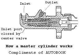
As soon as pressure is applied to the brake pedal, it pushes the pushrod, which in turn starts pushing the piston down the cylinder bore. As soon as the main spring pressure has been overcome, the valve stem floats freely in the piston. The bent washer acts like a spring pushing against the spacer and forcing the valve and seal to cover the reservoir port. As the pressure is increased on the brake pedal, the piston continues its travel down the bore, building up pressure in the fluid. Some pressure presses against the back of the valve to help keep it closed, while some of the pressure is transmitted out the brake line port to the wheel cylinders.
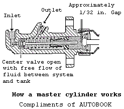 As the pressure on the brake pedal is released, the piston is
pushed up the bore by the spring. When the piston is just about at the end
of the bore, the valve stem has come out of the piston and has hit the
retainer/thimble. This will pull the valve and seal back into the spacer
and open the reservoir port. Brake fluid can move freely between the
hydraulic lines, master cylinder and the reservoir.
Now that the parts have been rebuilt, place the piston assembly
back in the master cylinder, replace the pushrod and washer and the
circlip. If the rebuild kit came with "brake grease" put it in the dust
cover and fit the cover over the pushrod and on to the master cylinder.

Drum Brakes

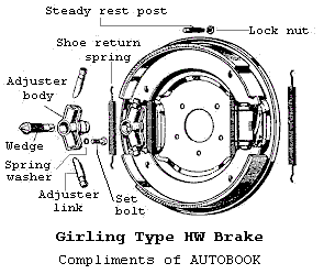 Rebuilding the drum brakes consists of replacing the brake shoes,
rebuilding or replacing the wheel cylinders, turning the drum (if required)
and adjusting the brakes for each wheel. On my '65 Morgan, only the rear
brakes use drums.
Start by jacking up the car, placing it on jack stands and chalking
the front wheels. Make sure the emergency brake is OFF. Next turn the
brake adjuster bolt fully counter clockwise to retract the brake shoes. To
remove the brake drum, unscrew the four hex bolts (some cars have 2 screws)
which hold the drum to the hub. The drum may need some gentle coaxing to
get it off the hub. This can be accomplished by tapping the inner edge
(nearest the backing plate) with a small hammer (a 5 pound sledge usually
works, Ha, Ha). To remove the brake shoes, first remove the steady rest
pin (see parts information below) from one of the two shoes. Using a pair
of slip joint pliers hold the outer retainer. Press inward to compress the
spring and turn the retainer 1/4 of a turn to release the retainer from the
pin. This will allow the brake shoe to be removed from the adjuster and the
wheel cylinder and relieve the tension in the springs. Unhook the springs
and the steady rest from the other shoe.

 Wheel Cylinders

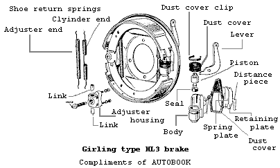
Rebuilding a brake wheel cylinder (see parts information below) is
easier if it is off the car. This is accomplished by disconnecting the
metal hydraulic line, the emergency brake linkage from the lever, removing
the dust cover (if there is one) and removing the metal spring clips that
hold the wheel cylinder to the backing plate. I spent about 45 minutes
trying to find an easy way to remove these clips. My conclusion was: there
is no easy way! Therefore, before you start take a break, have a glass of
water (well maybe a beer or two) and load up your vocabulary with 4 letter
words. You'll need a lot of them! Examine the way your clips are
installed. One clip has two lips that fit into notches on the 2nd clip.
The lips must be pressed under the 2nd clip so it can be slid back, off the
wheel cylinder. To remove the inner clip, the emergency brake lever may
have to be removed. To accomplish this, lift up on the wheel cylinder and
press the lever from the back of the backing plate. The lever has two rods
that slip into groves cut in the wheel cylinder. Once the lever is
removed, the other clip can be slid off.
To remove the piston, remove the clip that holds the dust cover over the piston, the dust cover, and finally the piston from the bore. The same procedure of using the compressed air (described above) may be required to get the piston out of the wheel cylinder.
Once the piston is out of the cylinder, the cylinder can be honed and the piston polished. The old seal can be removed from the piston. The new seal should be soaked in clean brake fluid before it is installed. Then it can be slipped onto the piston. Ensure that the flat side of the seal faces the piston.
The cylinder can be cleaned in VARASOL, washed off with water and dried off. The cylinder should be honed to remove any scratches and debris, then washed out using some brake fluid.
Reassemble the cylinder and set it on the backing plate. Install the holding clips. If you remember how they came apart, then reassemble them that way. However, it has been 2 years since I took mine apart and I forgot how they were placed. Various diagrams about the brakes show the inner clip (the one with the lips) being pushed on to the wheel cylinder from the side opposite the emergency brake lever. I tried this, but could not get the outer clip past the emergency brake lever. Consequently the following description is how I reassembled mine. Replace the inner holding clip (the one with the lips) by pushing it onto the wheel cylinder from the side of the wheel cylinder where the lever for the emergency brake is. Next install the emergency brake lever by inserting it from the front (outer) side of the backing plate. The outer clip can be slid on and pressed in until it SNAPS into place. The dust cover can now be slid over the emergency brake lever and around outside of the wheel cylinder retaining clips.
To install the brake shoes, I found it easier to set the shoe in place which presses against the back of the wheel cylinder. Then insert the steady rest pin assembly to hold the shoe to the backing plate. (This is a little tricky one handed. If you're lucky or a contortionist you can hold the shoe in place with your knee). Insert the steady rest pin from the back side of the backing plate. Then install one of the retainers, flat side against the brake shoe, then set on the spring. Hold the outer retainer with a pair of slip joint pliers and press inward to compress the spring. Once the pin is through the slot in the retainer, twist the retainer 90 degrees to the locking notch.
Hook the two return springs to the installed shoe. (The spring that is not coiled in the middle goes next to the wheel cylinder.) The springs can easily be hooked to the unmounted shoe. Now pull the end of the free shoe into its seat in the brake adjuster, then pull the other end into its seat in the wheel cylinder piston. This shoe must be held against the backing plate until the steady rest can be installed.
Replace the drum and the wheel. To adjust the brakes, turn the adjuster clockwise until the brakes start to touch the wheel. To determine this, spin the wheel. If it doesn't turn freely then back off the adjuster and try again. (Note: the adjuster is a square cut wedge. Consequently, the shoes will bind against the drum when the brake adjuster links are on the peaks of the wedge. Ensure that you are on a flat side. As you turn the adjuster, you will feel a "click" as you pass over the edges on the wedge.)
Continue on to Part 2
Return to theIndex of Tech. articles
To email me with comments or questions.