 tension. Too little tension and the front will sag. Too much tension may
snap the stay. Tension in the cross-axle stays should be adjusted before having
the front end aligned, and checked after alignment.
tension. Too little tension and the front will sag. Too much tension may
snap the stay. Tension in the cross-axle stays should be adjusted before having
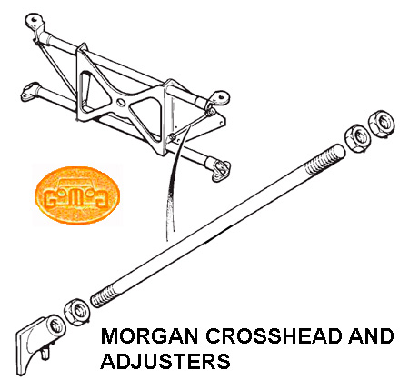
the front end aligned, and checked after alignment.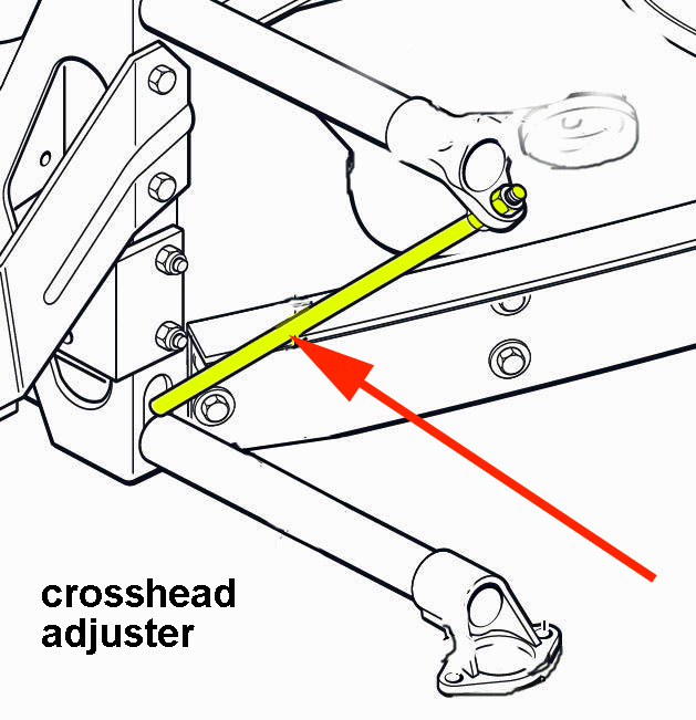 Crossframe (aka crosshead) Stay Adjustment
The purpose of the cross-axle stays is to triangulate the
cross-axle beams into a rigid structure, and thus prevent flexing during bump
and rebound. The cross-axle stays are adjusted so that they are always in
tension. Too little tension and the front will sag. Too much tension may
snap the stay. Tension in the cross-axle stays should be adjusted before having
the front end aligned, and checked after alignment.
2. Jack on the outer end of one side SLOWLY. The cross-axle should lift simultaneously from both the inner and outer stands (see sketch).
3. If the cross-axle lifts from the outer stand first, the cross-axle stay is too loose. Care should be taken not to jack the car too far off the stands. 1/2" to 1" should be sufficient. If the outer end is more than 1/4" off of the stand and the inner end has not lifted yet, the stay is much too loose.
4. Tighten the cross-axle stay until the cross-axle lifts off of both stands simultaneously. The cross-axle is properly tensioned. No advantage is to be had by significantly increasing the tension.
5. Repeat the above steps for the other side.
Adjusting Headlamps
by Lorne Goldman
Adjusting the headlamps on your Morgan is a relatively simple task. All you need is a screwdriver and a wall to shine the lights on.
Park the car about three feet from your garage door (or other wall) with the lights on low beam. You may need to do this at dusk or even in the dark to tell exactly where the light is shining on the wall.
Mark the outline of the beam shining on the wall with a pencil and them move the car back 25 feet from the wall. The top of the low beam should be no higher than the top of the circle on the door, and no lower than the center of the circle.
Remove the headlamp chrome surround. (see below) If the beam shines outside the circle, use the screwdriver to turn the adjustment screws on either side and above the headlamp housing. Turning the screws will cause the beam to move left to right, or up and down on the wall. A little experimenting will show you how to adjust the lights to fit the marks on the wall.
 Once the low beams are adjusted, the
high beams should be in the right spot also.
Once the low beams are adjusted, the
high beams should be in the right spot also.
If you install halogen headlamps, you will find that the
highly concentrated, white beam does an excellent job of illuminating the
road at night. However, halogen lights must be adjusted more precisely, because
the beam is more concentrated and there is less margin for error.
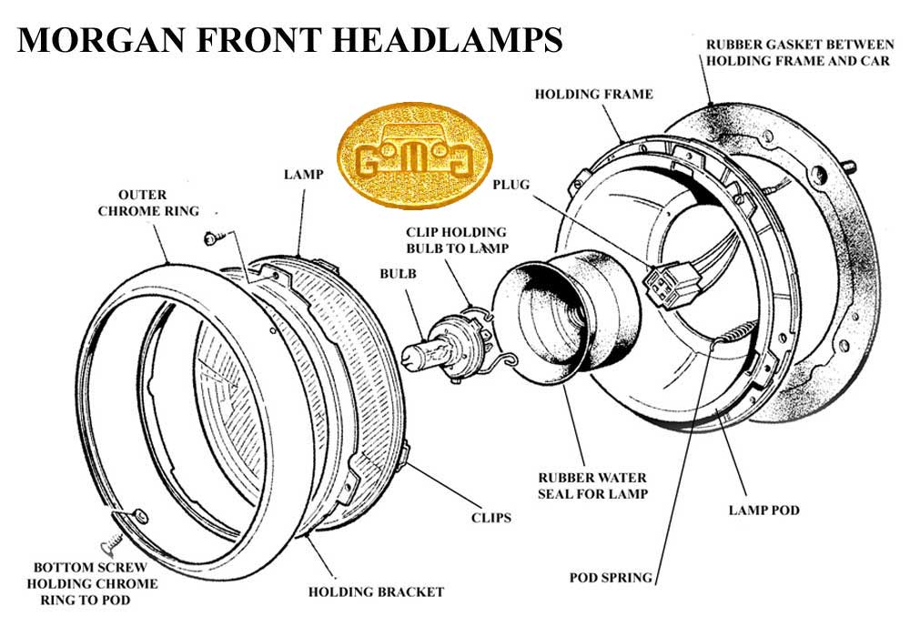
Removing the Headlamps
Headlamps changed. Most units are order by those pre-1981
(Lucas sealed beams), then 1981-1987, then 1987-1/1995 (Lucas
H4 Type or Lucas Domed Glass) and then 2/1995 on (WIPACs).
Of course, they come in RHD and LHD and are not adjustable from one to other
like the higher quality aftermarket offerings. Most are removable the same
way. One removes the outer chrome ring by removing a little holding screw
found at the bottom of the ring and slightly to the right. Once
out, the surround can be removed with a bit of finger pressure outward on
the ring. This exposes both the beam adjustment screws (Up & Down and
Right & Left) and the screws that hold the entire headlamp assembly to
the Morgan wing headlamp cans. Now remove the plug (and the silly "sidelamp" connection
and the headlamp comes out. Reassembly is the the reverse of disassembly.
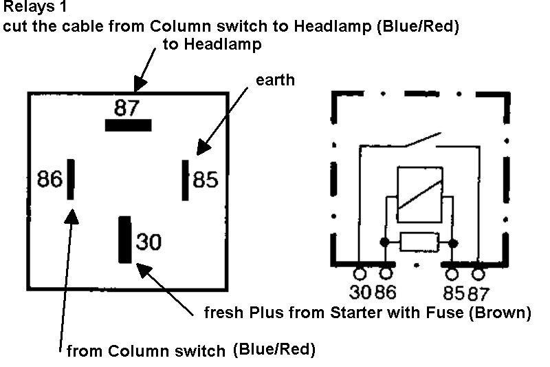
Having the Headlamps and Other Lighting Turn Off With the Ignition Switch
by André Koopmann & Lorne Goldman
We recently received a request from an owner on how he could rewire the lights to turn off with the ignition. It is not a complicated matter. One merely uses relays to transfer each power souce of the relevant lights (parking lights, dim beams, high beams and dash lights where relevant) from battery power to ignition switched power. Here are three diagrams from André that explain how it is done. Click each for a larger version.
 |
 |
|
Grease Points
by Greg Kaufman for the GoMoG Morgan Wire 2002
Spring has arrived, finally! And as a helpful thought when getting the Moggie ready for the first drive of the season don't forget to lubricate those grease fittings. And to help here is a list of them.
4 on the steering rack or steering
mechanism (Tie rod ends and et al)
2 on the bottom of the front suspension
2 inboard of the rear brake drums (very
sparingly please)
2 on the u-joints
2 on the pedal cluster**
1 on the spline shaft
1 on the transmission tunnel, up by
the firewall**
1 on the water pump
a drop of oil in each door
hinge, on any linkage and dab behind the knees.
Does one lubricate your pedal assembly!
Early cars have 2 grease fittings on it. One is on the /brake pedal
itself and the other is on the clutch pedal shaft support all the way on
the left end of the pedal assembly. There are also two more fittings
that need to be lubricated. One is located under the center of the crossmember
at the base of the firewall. It must be reached from underneath the car, and
lubricates the right hand end of the clutch pedal shaft. The other
is reached through a hole in the top center of the transmission cover once
the upholstery is removed from the metal transmission tunnel cover.
It is forward of the access hole about 2 inches or so and is aimed up at a
45 degrees angle so that it can be reached with a grease gun through the
access hole. This lubricates the throw out bearing where it slides back
and forth in the bell housing.
Later cars have no fittings but
I find the pedal assembly benefits from a spray of light lubricant. I dislike
a squeaking Morgan.
A DESIGN PROBLEM FOR THE WIPERS ON LEFT-HAND MORGANS
In the case of a right-handed drive Morgan the end of the wiper cable protrudes from its housing around the steering column and cannot be interfered with. In a left-hand drive Morgan, the cable housing and cable protrude into the upper glove compartment. At the end of the cable is a positioning spring which can easily get caught in gloves or scarves you might stuff in the compartment. The turning effect when the wipers are used binds the materiel into the spring...and forces the wiper motor to overheat and fail and that is very very expensive.
To avoid this problem...cut a small
section of sufficiently wide to cover the spring and the housing. Slide some
small rubber washers on the housing section and slide the pipe over these
washers (to reduce vibration and force the pipe back into position if moved)
and then use a clip to hold the pipe and screw it into the wooden member
immediately above.
THE PLUS 8 IGNITION SWITCH FOR LEFT-HAND MORGANS
by Lorne Goldman
Another under the dash anomaly with left-handed Morgans is the ignition setup. For example, on the Plus 8s a standard Rover ignition key setup is used. This is installed long before the bulkhead and dash on the steering column by fitting the piece around the column and then screwing in two screws from the bottom upwards to clamp it in place and then breaking these screws inside the fitting. If you ever want to remove the item...an extractor is used to remove the sheered screws and new ones are used for the re-installation.
With left-handed cars, instead of using left-hand ignition switches, Morgan uses the right hand switches upside-down as these must be installed on the other side of the column which means the screws are installed from the top downwards. After the bulkhead, dash and wiring is installed it becomes impossible to use an extractor to remove the screws and ignition switch. It is a fiddle to replace it if possible. The old one can be ground off (be careful) or you can drop the steering column to obtain access.
IGNITION SWITCHES (1970S to early
1980s)
by Lorne Goldman
Those running 1970's and early 80's Morgans with the Neimann ignition switch (as per p.88 of the John Worrall/Liz Turner book) may like to know that the ignition switch was fitted to both MGBs and several cars in the Vauxhall range.
I thought I'd post this as the factory has run out and the factory told me that it is unlikely that Neimann will make another batch! So try your local scrap yard!
Regards, Arwyn
IMMOBILIZER ISSUE
by Lorne Goldman July
31, 2008 and updated by Mike Elston October 17, 2016
GoMoG has run across a number of 4/4s with an immobilizer issues. The Ford Morgans from 1999 use a key that is a melange of efforts and designs from 4-5 companies; Ford, Land Rover, Valeo, Morgan and likely another aftermarket supplier. In other words, it is not as solid as it could be. The keys are made by Valeo to LR specs but the security system (immobilizer) is Ford, represented by a chip glued in position to the key. When the little chip falls off, the key will not start your Morgan. If you find it, you can re-glue it on and all's well. In
So point one is to check your keys and their chips. It would be wise to carry a tube of instant glue and a spare key because the only instant solution to a missing chip is another key or a long tow home.
If you have lost the chip or want a spare, you have two options (or less outside the UK). You can contact the Factory. They will normally offer you or dealer a full new key ignition system (with new keys) This is very costly and a long install. However, the parts for the key only are MDE1986 (the key) and MDE1987 and you can have your dealer to specifically order these only. If this works, it is a convenient but still very expensive.
However, any decent locksmith can help you out. Once they know where the key comes from (above) they can get a "blank" in no time for your existing keys (at least in the UK). I have been told by a number of dealers that it is easy for a locksmith to work out how to attach the Ford chip (for a negligible cost).
To program the new key, take the master key and insert it three times into the ignition, then insert the newly made for Morgan key. This will transfer the programming from the master to the new key's chip.
Mike has combed the Ford forums and found that if you turn the ignition on, the light will flash rapidly. Leave the light flashing for a minute. These flashes indicate numbers for diagnostic codes. For example, 1 flash ( pause ) then 5 flashes -- this indicates flash code 15. And here is what some mean.
Alarm Flash Codes