The Morgan Brake System
by Lorne Goldman
The brakes and tyres are the most important components on your car. If either fail, the result
can be disastrous. Brakes are actually energy conversion devices,
converting kinetic energy (momentum) of your vehicle into thermal
energy (heat).
When you step on the brakes, you command a stopping force ten times as
powerful
as the force that puts the car in motion. So the braking system exerts thousands
of pounds of pressure on each of the four brakes. Many electric cars now preserve that braking energy temporarily so as the release it immediately after for creating incredible start-off times!
| WATCHPOINT Since 1968 (Plus
8s) or 1978 (all cars) Morgans have been fitted with dual circuit master
cylinder systems, with each the front and the rear wheels braked by a separate
subsystem. That way, if one subsystem fails, the other can provide life-saving
braking power. These are infinitely safer than earlier braking systems. I
counsel you to ignore or caution anyone who suggests a single circuit system
be maintained rather than replaced. |
But the basic
process
of converting a vehicle's momentum into (wasted) heat energy has not
changed
since the days of the horse and buggy. To stop a horse drawn carriage,
the
driver would pull on a lever which would rub on the wheel. A good
braking system reflects the mass of the vehicle as the needed braking
energy is a function of of the size of that mass and balance.
EDITORIAL NOTE:
Outside of the simplicity and purity of their design, trad
Morgans set themselves apart from most automobiles by their very low
weight. HFS, a canny engineer of the Old School, knew that simplicity,
low weight and potent engine could beat all comers on the racing and
autocross competition. The early Morgan record in those fields is
remarkable. Even today, in their class, the 1968-70 Plus 8s are the
cars to beat in an all marque competition of that era!
But today's flock of moggers have lost their way on the braking side, as they have in other areas. :(
Very low mass means much less braking power is necessary. But that is
ignored by today's community. Even rear disk brakes are added when they
make no sense. They remind me of the true tale that Peter Morgan
prominently added front dampers only because they pleased the
sensibilities of the post-shock customers! (One day you should all remove the front dampers for a test ride. You will be surprised.) Morgans
don't need much braking. Front disks and rear drums are more than
sufficient for any road-going trad going Morgan and MOST racers I have
ever seen. The tedious expensive installation of rear disk brakes often
unbalances the braking again, making the comportment of the car harder
to control and often at the cost of a functional safety brake. We can
also theorize that the weight distribution of the unsprung weight
prejudices the perfect weight of the trad.
WATCHPOINT 1: The balance proportioning of the pre-1993 systems should be verified and corrected or click here as well. The
set up of the dual cylinder Girlings is incorrect for our cars. It was
correct when Bill Beck had the later AC power assisted system installed
in all the cars.
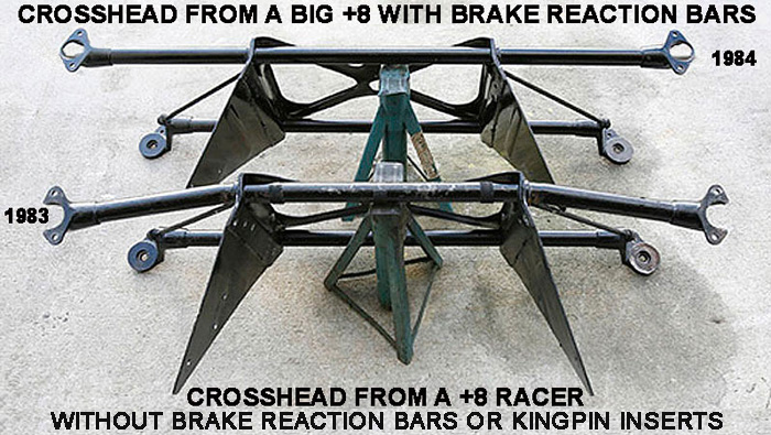
WATCHPOINT 2: The
design of the front end creates an unsteady hard-to-control factor on
hard braking. It so potent that eventually it bows the cross
member!! It can be easily/cheaply rectified in two ways..one goodThe
bad one is ingenious and simple! One bangs old kingpins down the lower
crossmember piece to stiffen it and prevent its bending. It also stops
the unsteadiness on hard braking. However, it add LOTS of weight at the
very periphery of the car, exactly where you DO NOT want it..like
putting a heavy case on the rear does.
WATCHPOINT 3:
I HAVE found a potent improvement in merely choosing better brake pad
and drum show improvement. Thpugh those chosen by some national
communities have a sad if any effect. Porterfields and one bad.
will change the effective braking of two pot braking (assuming the
rear shoes are done as well) to the effectiveness of the later 4 pot
calipers.
 |
|
The brake system is
composed of the following basic components: The "master cylinder" which is
located under the hood, and is directly connected to the brake pedal, converts
your foot's mechanical pressure into hydraulic pressure. Steel "brake lines"
and flexible "brake hoses" connect the master cylinder to the "slave cylinders"
located at the wheel. Brake fluid, specially designed to work in extreme
conditions, fills the system. "Shoes" and "pads" are pushed by the slave
cylinders to contact the "drums" and/or "rotors" (discs) thus causing drag,
which (hopefully) slows the car.
Disc brakes have been
used for years for front wheel applications, (and on many older cars are
fast replacing drum brakes on the rear wheels). This is generally due to
their simpler design, lighter weight and better braking performance. The
greatest advantage of disc brakes is that they provide significantly better
resistance to "brake fade" compared to drum type braking systems. Brake fade
is a temporary condition caused by high temperatures generated by repeated
hard braking. It occurs when the pads or shoes "glaze" due to the great pressure
and heat of hard use. Once they cool, the condition subsides. Disc brakes
allow greater air ventilation (cooling) compared to drum brakes. Drum brakes
are not internally ventilated because if they were, water could accumulate
in them. Disc brakes can rapidly fling off any water that they are exposed
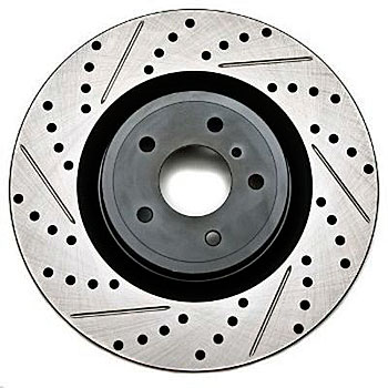
to, and so they can be well ventilated. Morgan rotor (discs) are quite thick
which requires higher temperatures to heat but are also difficult to cool
for the same reason. High performance disc brakes have drilled or slotted
holes through the face of the rotor, which helps to prevent the pads from
"glazing" (becoming hardened due to heat). Many suppliers sell ventilated
discs for racing applications.
Disc
Brakes
by Lorne Goldman
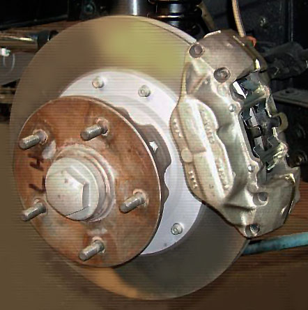
Disc brakes use a
clamping action to produce friction between the "rotor" and the "pads" mounted
in the "caliper" attached to the suspension members. Inside the calipers,
pistons press against the pads due to pressure generated in the master cylinder.
The pads then rub against the rotor, slowing the vehicle. Disc brakes work
using much the same basic principle as the brakes on a bicycle; as the caliper
pinches the wheel with pads on both sides, it slows the bicycle. Disc brakes
offer higher performance braking simpler design, lighter weight, and better
resistance to water interference than drum brakes.
Disc brakes, like
many automotive innovations, were originally developed for auto racing, but
are now standard equipment on the front wheels of all Morgans and the rear
brakes are of the "drum" type. Drum brakes use two semi-circular shoes to
press outward against the inner surfaces of a steel drum. The older cars
have drum brakes on all four wheels and their are suppliers who sell
a rear disc brake conversion kit.
Because disc brakes
can fling off water more easily than drum brakes, they work much better in
wet conditions. This is not to say that water does not affect them, it definitely
does. If you splash through a puddle and then try to apply the brakes, your
brakes may not work at all for a few seconds! Disc brakes also allow better
airflow cooling, which also increases their effectiveness.
Rotors
(Discs)
by Lorne Goldman
The rotor (also
called the disc) is clamped by the brake pads in order to slow the vehicle. The rotor is a
heavy circular steel plate attached to the wheel providing a two sided braking surface.
Pressurized fluid in the brake lines flows into
one or more "slave" cylinders in each caliper. The fluid pressure is
exerted against the slave pistons, which force the brake pads against the
surface of the disc. As the pads clamp onto the rotor, intense heat is
generated, which can in extreme conditions actually cause the rotor to glow red
hot, affect the nearby ignition coil and the ENGINE!
!
The surfaces of the
rotor are "turned" (re-machined) whenever the brake pads are replaced in
order to remove the "glazed" surface which forms on the rotors. The turning
process also "trues" the disc (makes it perfectly flat) which eliminates
the pulsations which are experienced when the rotor is warped. Warped rotors
give a slight tugging when the brakes are applied, and send a pulsing sensation
back through the brake pedal. Rotors have "minimum thickness" and if it is
"turned" to resurface, it may become too thin to withstand heat as it warms,
requiring replacement. In fact, the ability of the discs to resist heat is prejudiced
before they ever reach the minimums. In my book, that makes skimming Morgan discs like
one does with other cars, a losing game..especially as the odd Morgan discs are not easily available at every brake
shop. Maximum run-out on the rotor faces is only .002 inches (.0508 mm). The maximum
permissible finish of the disc machining is 15-30
micro inches circumferentially and 50 micro inches measured laterally, merely one very
thin cut (if that) that might last a very short while unless your usage is negible. When you get
near these limits, a skimming of
the disks won't help you for long. I tried that once and they lasted 10 minutes! I DO NOT skim my Morgan disks. I replace them. Why ruin a vacation
of a outing because you wanted to save a few pennies? That being said, aside from trying to skim the used
disks of my first Morgan at 30k, I have never had to replace from disks. It is all in the matter
of how you drive your Morgans. I do not use my brakes much. 95% rural driving. I haven't used my backup new
disks on three Morgan Plus 8s over the last 30 years and 250,000 miles.
Pre-1992 4/4 and Plus 4s arrive new at .375, later models and Plus 8 start at .500". Please
note that Morgan Discs/Rotors are specially ordered by the Company, if you find
a suitable replacement please email
me.
(Semi metallic brake
pads give better performance, longer replacement intervals and reduced "fade",
but they also wear down the rotor more quickly than organic [non-metallic]
pads.) Recently, I decided to try Carbon Kevlar pads and and rear shoes and
I am very pleased with the difference. The braking has more "feel" and is
far more effective in all conditions.... no squeaking either! I use Porterfield R4-S
THE
TEN COMMANDMENTS OF DISC BRAKES
1. A brake disc is
one of a vehicle's active safety components. Competence and constant technical
updating is therefore essential for anyone dealing with it.
2. It is appropriate
to regularly check the disc thickness and appearance. A change must be made
before the disc thickness reaches its minimum value (thickness) [.450 inch
on a Plus 8 or post-1992 4/4 or Plus 4], or whenever anomalies are noted
on the disc surface. The thickness of the rotor indicates how resistant it
will be to the high heat of its use. Below a certain point, it will not be
able to stay true for any period.
3. The disc assembly
instructions must be read and scrupulously followed at all times.
4. Discs on the same
axle must always be changed together.
5. Brake pads must
be changed together with the discs. The correct choice of pads is essential
for braking efficiency and comfort.
6. The discs and pads
being replaced are an important source of information. Always carefully inspect
the disc condition (condition of the braking surfaces, colors, appearance,
etc.). This may show anomalies in one or more components (calipers,
pads, bearings), and before changing the discs any such problems
should be identified
and solved.
7. Clean the disc
and most important the hub surface, and remove any traces of corrosion.
8. Properly tighten
the bearing nut and replace the pin with a new one. Properly tighten the
fastening bolts in a cross-wise order using a torque wrench to check to applied
torque. The same instruction goes for installing the wheel.
9. Check the run-out
of the brake disc, by using a run-out gauge attached to a fixed part of the
suspension.
10. In order to allow
a perfect fit of the materials and guarantee top performance, observe
a short running-in period (180-300 miles), using only regular and smooth
braking action.
DRILLED, SLOTTED & SMOOTH ROTORS (BRAKE DISCS) by Lorne Goldman
 Without question, brakes are the most powerful system on your vehicle. No matter how much horsepower
you have, none of it’s of any use if you can’t brake off enough speed to keep from rear-ending the car in front of you. On the other hand,
traditional Morgans are so light that braking is never a large task,
with the
codicil that the front becomes unsteady on hard braking and brake reaction bars become an inexpensive and smart idea. The factory brakes
provide ample stopping power for regular road driving.
Without question, brakes are the most powerful system on your vehicle. No matter how much horsepower
you have, none of it’s of any use if you can’t brake off enough speed to keep from rear-ending the car in front of you. On the other hand,
traditional Morgans are so light that braking is never a large task,
with the
codicil that the front becomes unsteady on hard braking and brake reaction bars become an inexpensive and smart idea. The factory brakes
provide ample stopping power for regular road driving.
Here is the analysis.
Smooth Brake Rotors
A premium set of smooth
rotors provides more than enough stopping power under normal driving
conditions. They provide the most surface area where drilled
and slotted rotors reduce it. They also are very effective at acting as
a heat-sink, which is exactly what a brake rotor was designed to do.
They’re also not as
prone to cracking under extreme use unlike drilled rotors can be. The absence of slots or
drill holes allows smooth rotors to maintain maximum structural
stability and integrity, making them suitable for moderate track use
when paired with performance brake pads and high-boiling point brake
fluid.
Slotted Brake Rotors
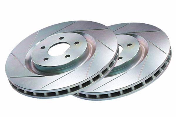
Slotted
rotors, as the name implies, have grooves cut along the face of the
rotor where the pad makes contact. This is because under repeated heavy
braking, as the temperature of your brake system increases, a layer of
gas and dust forms between the pad and rotor from the material transfer
caused by friction. The slots in the rotor allow an escape route for the
built-up gases. This allows more of the brake pad’s surface area to
contact the rotor, resulting in better pad bite and more consistent
stops. Also, this increased surface contact results in a higher
coefficient of friction, so you’re actually using less energy to slow
your vehicle the same amount. The venting provided by slotted rotors is
one of the main ways to combat brake fade and maintain consistent
stopping power, lap after lap. Slotted
and drilled brake rotors help evacuate those gases and dust, shed
heat, and keep the pad from "glazing" by keeping the brake pad surface
clean. And on wet surfaces and/or raining conditions, slots and cross-drilled holes can help push water off the braking surface for better stopping power.
| WATCHPOINT: Some dedicated
slotted “racing” rotors employ a sharp edge on the slots to cut
into the brake pad a small amount for better bite, but this can greatly
accelerate brake wear. |
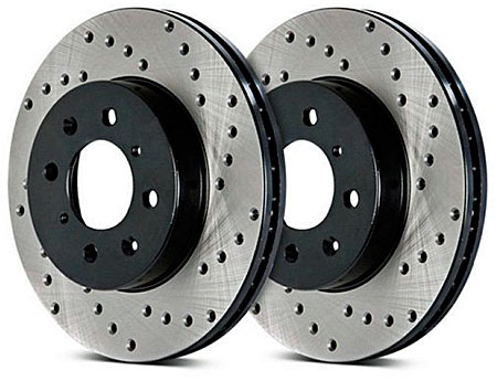
 Cross Drilled Brake Rotors
Cross-drilled
brake rotors look undeniably cool peeking out from behind a set of
wire wheels and they keep your brakes the same way – cool. In the
early days of racing, drilled rotors were an effective way of venting
the layer of gas and dust that inevitably builds up between asbestos
brake pads and the rotor under repeated, hard braking. However, as technology and brake pad materials have progressed (see brake pads) venting gas has
become less of an issue. These days, while they still look
great and perform well, the drill holes are more for aesthetic reasons
than anything else. For performance driving, slotted rotors have become
the preferred choice because cross drilled rotors are more prone to
stress cracking under extreme use.
Just take a look through the spokes on the wheel of any modern race car
– there won’t be a drilled rotor in sight. And, for street
driving, the temperatures your brakes encounter never even come
close to the levels they do on the track. So, the venting properties of
drilled rotors offer the added benefits of keeping temperatures down
under normal driving for prolonged pad life, as well as improved
wet-weather performance by allowing water to escape the rotor’s
surface, increasing initial pad bite.
Drilled & Slotted Brake Rotors
Drilled and
slotted rotors provide the looks and functionality of both cross-drilled
rotors and slotted rotors combined. However, they are still not ideal for the abuse
they would suffer on vigorous breaking (i.e. the drill holes being prone to
stress-cracking). See Drilled rotors above.
CONCLUSION: Choosing the Right Brake Rotor
There are a few things to keep
in mind when choosing cross drilled or slotted brake rotors. For
street-driven vehicles, both perform equally well and don’t suffer any
detrimental side effects aside from those mentioned. Slotted or cross drilled rotors will not decrease your vehicle’s original stopping distance.
Their purpose is to dissipate heat and gases to combat brake fade and
provide consistent stops after prolonged abuse. In order to take a
sizeable chunk out of your stopping distances, a set of sticky tires
and dedicated high performance brake pads are the recommended
upgrades. For eye-catching, high-end style, drilled or drilled &
slotted rotors are sure to turn heads. For daily driving, any of the
above provide more than enough stopping power, especially on the MUCH
lighter traditional Morgans. All the being said, the steadier feeling
slots offer in the rain and wet surfaces is an improvement for Morgans,
which are very sensitive to road conditions.
Brake
Pedal
by Lorne Goldman
The brake pedal, (in
case you're one of those people who don't use it), is located between the
accelerator pedal and the clutch. The brake pedal is connected to the master
cylinder via a push rod which has a "slack" adjuster fitting to properly
adjust the brake pedal relationship to the push rod.
The brake pedal is
solidly mounted to the firewall, and works as a force multiplying lever.
Stepping on the brake pedal pushes a piston within the master cylinder, thereby
pressurizing the hydraulic brake lines. The hydraulic pressure pushes the
brake shoes and pads against the brake drums and rotors, thus slowing the
wheels.
The brake pedal gives
feedback to the driver which can be beneficial to good maintenance, and therefore
potentially save your life. If the pedal pulses when pressed, the usual culprit
is a warped rotor, which is potentially destructive to the caliper. If the
pedal squishes down when pressure is applied, a dangerous leak is likely
present (even if fluid does not drip out anywhere). Your brake pedal should
not move more than a small amount when you press it, no matter how hard it
is pressed. It should not feel sponge like: a spongy pedal spells trouble
in the braking system. With the car parked, press the brake pedal firmly
and hold the pressure. If the pedal sinks slowly, a leak is present.
A good rule of thumb
is this: ANY changes in the "feel" of your brake pedal should be a cause
for serious concern. Remember, with brakes, there is NO excuse for poor maintenance.
Brake
Drums (generally)
The brake drum is
a heavy flat-topped cylinder, which is sandwiched between the wheel rim and
the wheel hub. The inside surface of the drum is acted upon by the linings
of the brake shoes. When the brakes are applied, the brake shoes are forced
into contact with the inside surface of the brake drums to slow the rotation
of the wheels.
They are not cooled
internally, because water could enter through the air vent cooling holes
and braking would then be greatly impaired.
One advantage of drum
brakes is that they can easily be set up to be mechanically activated by
a pull cable (for use as parking brakes). Drum brakes are usually quite sufficient
for rear brakes because most of the car's weight transfers to the front wheels
during hard braking. The reduced weight on the rear wheels makes the higher
performance of disc brakes somewhat unnecessary except in racing.
The working parts
of a drum brake are contained inside the brake drum. The drum is attached
to the hub of the wheel and revolves with it. Inside the drum are a pair
of curved brake shoes that are held close to the drum by retractor springs.
The shoes and actuator linkages are mounted to the backing plate behind the
drum. When the brake pedal is pressed, fluid is pressurized in the wheel
cylinders. Pistons in the wheel cylinders then push outwards against both
shoes, overcoming the retractor spring tension and pressing the shoes against
the drum. The friction of the shoes against the drum slows the wheel. When
pressure is released from the brake pedal, the retractor springs force the
shoes back to their normal (released) position. The springs force the brake
shoes slightly back (inward) away from the drum when the brake is released.
These springs, along with the other brake hardware, should be replaced every
other time the brake shoes are replaced.
As the linings of
the shoes wear down and become thinner, an adjustment screw must be used
to keep the shoes close to the drum but without touching until applied.
Back
Plate
by Lorne
Goldman
The backing plate
is a round, stamped steel disc, used to keep water out of the drum/rotor,
and in drum brakes as a mount for the wheel cylinder. It is bolted to the
end of the rear axle housing. The backing plate is the foundation for the
wheel cylinder and brake shoe assembly. By the way, the racers prefer they
older adjustable rear brakes (pre-7/1993) to the later self-adjusting brakes
used after.
Anchor Pins and Shoe Retainers
The anchor pin is
a strong metal pin mounted to the backing plate, which prevents the shoes
from turning along with the wheel when the brakes are applied. Shoe retainers
are small spring clips of various designs used to hold the brake shoes against
the backing plate. These pins insure shoe alignment and prevent them from
rattling.
Wheel (Slave) Cylinders
Wheel cylinders, also
called the "slave" cylinders, are cylinders in which movable piston(s) convert
hydraulic brake fluid pressure into mechanical force. Hydraulic pressure
against the piston(s) within the wheel cylinder forces the brake shoes or
pads against the machined surfaces of the drum or rotor. There is one cylinder
for each wheel. Drum brake wheel cylinders are made up of a cylindrical casting,
an internal compression spring, two pistons and rubber cups or seals. This
type of wheel cylinder is fitted with push rods that extend from the outer
side of each piston through a rubber boot, where they bear against the brake
shoes. Only one of the Morgan rear wheel cylinders has a bleeder screw
(right hand side) (or bleeder valves) to allow the system to be purged
of air bubbles.
As the brake pedal
is depressed, it moves pistons within the master cylinder, pressurizing the
brake fluid in the brake lines and slave cylinders at each wheel. The fluid
pressure causes the wheel cylinders' pistons to move, which forces the shoes
against the brake drums. Drum brakes use return springs to pull the shoes
back away from the drum when the pressure is released.
N.B.
See the note on master cylinders 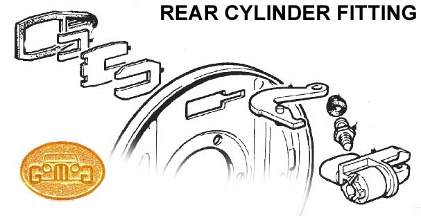
Removing Rear Slave Cylinders (pre-1993)
by Lorne
Goldman
Removing the Morgan
wheel cylinders can be a trick at first. The little shims/clips and doodads
are great fun. There are three of them holding the rear cylinder in its slot
(but allowing it to move in the slot). The two bigger ones nearer to the
back plate are U-shaped and (they come in from different ends) lock together
at one end with two locking tabs holding them together. This is extremely
hard to see the first time without 15 year old eyesight and an electron microscope.
First remove the third one which is the obvious outer one applying the pressure.
You may have to remove the parking brake lever to do this. After removing
this pressure shim, use a good light, and possibly a magnifying glass to
see the two locking pieces and the tabs..lifting the two apart at the locking
tabs with a very small screwdriver or even an exacto knife and then sliding
one (the lower?) back to disengage them.
Special Note on Wheel Cylinders!
by Lorne Goldman December 21, 2005
The Works has announced
that the Girling rear brake cylinders are no longer available and has sent
this information to their Agents. This crucial parts was/is used on the following
Morgans:
+4s 1958 to 7/1993
4/4s from 1960
to 7/1993
+8s from 1968
to 7/1993
In fact, there is
a readily available OEM match sourced by an eMOG member at a retailer. Here
are the details.
Pattern Rear Brake
Cylinders manufactured by Past Parts,
part no. 25-0146
They take Visa
and are willing to ship worldwide.
Cost is GBP 15.08.
Special Note on
Wheel Cylinders! (post-1993s)
by Lorne
Goldman June 2012
The wheel cylinders
are Caparo AP Braking CW 15953 which are matched by Delphi Lockheed LW 15953.
Notes
on Removing Morgan Brake Drums (Series V 4/4)
from Paul Helman
Those large screws
on the drum alone are not what you are looking for. All they do is
retain the drum to the hub. You should also be looking at those quarter inch
27/inch threaded hex bolts.
Try backing off all
the way on your adjuster screws then gentle tapping around the rim of the
drum (using a piece of wood between hammer and drum rim) should get it off.
I assume your basic configuration is similar to mine (Series V 4/4) which
I am currently redoing.
N.B. I suggest new
retaining bolts to avoid shearing off the bolt when retightening the drum.
(I did this twice recently necessitating removal of the hub and a bit of
careful drilling to extract the body of the bolt with a stud extractor without
damaging the thread of the mounting holes in the rim of the hub. These are
hardened bolts so it did present a challenge. I am getting somewhat
adept at it just through repetition..
Removal of the the
hub is easy once the drum is off by using a large gear puller. Hopefully
your cotter pin has been installed in such a manor that straightening it
will be no problem . Once the cotter pin is removed, the removal of
the castellated nut is no problem. This is what made 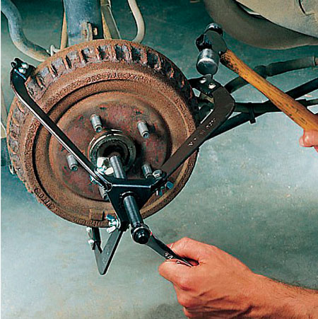 removal of the sheared
bolt relatively easy with the hub in hand and the careful use of a drill
press. This is not something to be tried with the hub still mounted.
removal of the sheared
bolt relatively easy with the hub in hand and the careful use of a drill
press. This is not something to be tried with the hub still mounted.
BRAKE DRUMS REMOVAL (pre-1993)
by George Dow at the
eMog Pub
Most old cars that
I have worked on have a securing screw that is usually done up too tight.
These screws are there to stop the drum coming off with the wheel when it
is changed, therefore do not need to be done up tight "too" tight at all.
If you have a suitably sized screwdriver that can take a hit on the handle,
put the driver in the screw head and give the screw a hit before you try
to loosen it (if you have such screws fitted) If that don't work.....an
impact driver might do the job. (Please remember to NOT use it to put them
back on! Some anti-seize on the threads can help next time you decide to
remove them.
First back off the adjuster (at the rear of the back plate) on these pre-1993 (Triumph rear brakes).
You can also borrow a brake drum puller. See method at the right
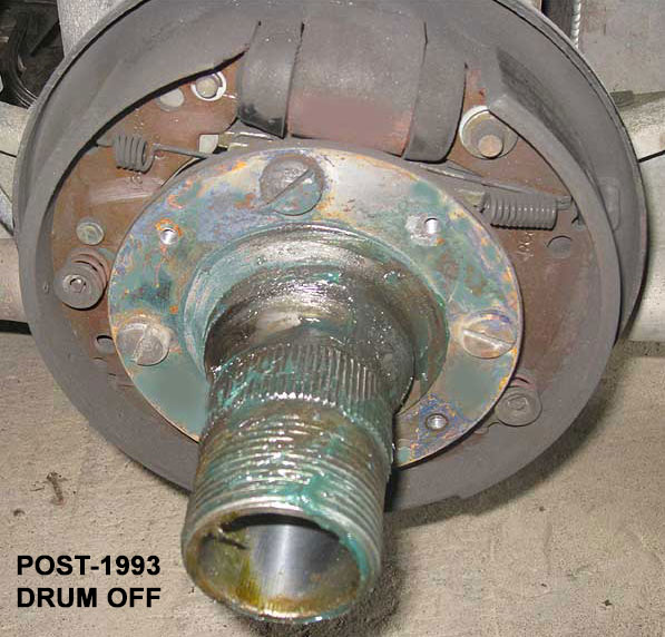
BRAKE DRUMS REMOVAL (post-1993)
by Lorne Goldman
years later
 George's instructions above
will pretty much do the trick. However, the post-1993 reardrums do NOT
have a post adjuster at the rear of the back plate. (for this reason
many racers move back to the earlier pre-1993 versions (if they are
lucky enough to find a back plate!). At one point, Librands was looking into having a better rear drum system made. Check with them.
George's instructions above
will pretty much do the trick. However, the post-1993 reardrums do NOT
have a post adjuster at the rear of the back plate. (for this reason
many racers move back to the earlier pre-1993 versions (if they are
lucky enough to find a back plate!). At one point, Librands was looking into having a better rear drum system made. Check with them.
Aside from terminal furstration occasioned by amateurs fitting a new
rear cylinder or shoes into this very fiddly system, many
mistakenly remove the hub fittings. These are the huge slotted fittings
that clear the drum and are visible from the outside. One would think
that even a first time cursory examation would show that these things
do not have anything to do with the drum at all, but this has not been
obvious to everyone. LEAVE THEM ALONE unless you wish to remove the hub
and drums off the axle, a very tough job needing a slide hammer.
To remove the drum, merely remove the little bolts and then bang the
drum outward (from their interior edge) with a rubber hammer .
Brake Calipers
The caliper works
like a C-clamp to pinch the pads onto the rotor. It straddles the rotor and
contains the hydraulic "slave cylinder" or "wheel cylinder" piston(s). One
caliper is mounted to the suspension members on each wheel. Brake hoses connect
the caliper to the brake lines leading to the master cylinder. A "bleeder
valve" is located on each caliper to allow air bubbles to be purged from
the system.
Morgan calipers contain
two (and recently four) separate pistons. These calipers are fixed in place;
i.e., there is no lateral movement like the newer floating caliper, the pistons
take up the slack on each side of the rotor. These are called "dual cylinder"
or "dual piston" calipers, and are standard equipment on many performance
cars.
Brake Pads and Brake Shoes
Brake pads and brake
shoes are composed of a friction lining material mounted onto metal backing
plates. Brake linings are designed to have a specific coefficient of friction.
The linings contact the drums and discs, create drag, and thereby retard
the speed of the vehicle. The lining material is designed to wear down faster
than the rotors and drums they rub against, so that they are the only part
that usually has to be replaced. When worn out pads and shoes are replaced,
the drums and rotors are re-machined or "turned" (a small amount of metal
is removed from their surfaces) so that the brake shoes and pads will "break
in" properly.
Because of intense
friction and heat produced in braking, brake linings were first composed
of heat resistant asbestos compound. When it was discovered that breathing
dust containing asbestos fibers cause serious bodily harm, asbestos pads
were replaced with other types. There are now three basic types of materials
used in brake linings: (1) non asbestos organic, which is usually made from
filler materials and high temperature resins; (2) metallic; and (3) semi
metallic, which are composed of finely powdered iron or copper, graphite,
and small amounts of inorganic filler and friction modifiers. The first and
third types of brake lining are used for conventional brake service. Under
extreme braking conditions (sports cars, ambulances, police cars), the metallic
type of linings are used, because they provide more constant frictional characteristics
(reduced brake fade) than the other two. Organic pads and shoes wear down
the rotors and drums less than semi metallic or metallic pads, but also wear
down quicker themselves, requiring more frequent replacement.
Most pads and shoes
have "wear indicators" built into them, or into the hardware which holds
them in place. The wear indicators cause a squealing noise when the linings
wear down to the level of the indicator. Mechanical wear indicators (small
metal tabs) allow the driver to know when their brakes are needing replacement
before serious damage occurs. When the pads or shoes wear out completely
(past the wear indicators) and the backing plates contact the drums or discs
for extended periods of time, the damage which results can require replacement
of the rotor or drum, which is MUCH more expensive than the shoes and/or
pads! (Some advanced braking systems have electronic wear indicators built
into the linings, which allow the driver to be warned by a light on the dash.)
Better
Pads and Shoe Compound
As noted above, I
decided to try carbon kevlar pads and and rear shoes and after search about
a bit. I am very pleased with the difference. I have experience with five
compounds used on Morgans.
MMC
STOCK PADS Caparo Brakes (post June 1993)
These have the braking
compound that will be provided by the MMC as original stock. They are the
bottom of the list for feel and effectiveness but are serviceable. The have
an infamous  tendency to squeal. They also do not fit properly requiring, on the advice of the supplier, remedial measures at your first service. Available from your Morgan dealer or off
ebay.co.uk.
tendency to squeal. They also do not fit properly requiring, on the advice of the supplier, remedial measures at your first service. Available from your Morgan dealer or off
ebay.co.uk.
GREEN STUFF
PADS
The UK community favors
EBC Green Stuff Pads. I tried them on our UK Plus 8. IMHO they are better
than the stock pad as they act normally when cold. But other than that they seem to be nowhere near as performant
as something made specifically for road going sports cars. On that point, I have never read anything noteworthy
about them in performance applications and I removed them after a single season.
However, they seem to wear well and make less noise than the stock pads. British Company
PORTERFIELD PADS
 I first bought these
24 years ago at the suggestion of John Sheally II, the racer. I started with their Brake
pads and then their shoes in the same compound 20 years ago (their R4-S
compound). I now swear by them. The braking has more "feel" and is far
more effective in all conditions.... no squealing either. To give you an
example, I found the 2 pots calipers had the same braking power as 4 pots
when the Porterfields were put on! US Company. And they seem to last forever!
I first bought these
24 years ago at the suggestion of John Sheally II, the racer. I started with their Brake
pads and then their shoes in the same compound 20 years ago (their R4-S
compound). I now swear by them. The braking has more "feel" and is far
more effective in all conditions.... no squealing either. To give you an
example, I found the 2 pots calipers had the same braking power as 4 pots
when the Porterfields were put on! US Company. And they seem to last forever!
Master
Cylinder (pre-1993) by Lorne
Goldman
The master cylinder
displaces hydraulic pressure to the rest of the brake system. It holds THE
most important fluid in your car, the brake fluid. It actually controls two
separate subsystems which are jointly activated by the brake pedal. This
is done so that in case a major leak occurs in one system, the other will
still function. N.B. We do NOT recommend the use of single circuit
masters used on pre-1978 cars. Their lack of any redundancy or safety measures
make them dangerous. The two sub-systems
should be supplied by separate fluid reservoirs or they may be supplied by
a common reservoir that is is split inside. The systems are divided front
and rear. When you press the brake pedal, a push rod connected to the pedal
moves the "primary piston" forward inside the master cylinder. The primary
piston activates one of the two subsystems. The hydraulic pressure created,
and the force of the primary piston spring, moves the secondary piston forward.
When the forward movement of the pistons causes their primary cups to cover
the bypass holes, hydraulic pressure builds up and is transmitted to the
wheel cylinders. When the brake pedal retracts, the pistons allow fluid from
the reservoir(s) to refill the chamber if needed. This is the system Morgan
used from 1970s on.. a Girling unit from 1978-1993 and then a AP Racing system
with an integrated booster.
On later models. if
the brake light comes on, the fluid level in the reservoir(s) should be checked.
If the level is low, more fluid should be added, and the leak should be found
and repaired as soon as possible. BE SURE TO USE THE RIGHT BRAKE FLUID (see brake fluids
and the note on Silicone fluid) FOR YOUR VEHICLE.
Switching to or from silicone brake fluid can contaminate the system. If
this occurs, ALL of the seals in the brake system will need replacement,
and that is usually a VERY expensive operation. The tandem master cylinder was devised to avoid the possibility of all
the brakes of a vehicle being put out of action by a fracture in the
pipe line leading to one brake cylinder. . There are two pistons in the
master cylinder, in line with each other.
Difficulty in fitting
brake lines to the master is due to the ends of the steel flares having been
squashed by over tightening. Girling calls for a tightening torque
of 15 inch lbs. The tube nuts should be able to be easily threaded
all the way into the master cylinder ports by fingers alone.
Replacement for the Morgan Dual Master Cylinder
(pre-1993)
WATCHPOINT: We are looking for other alternatives. Suggestions welcome! April 14, 2022
|
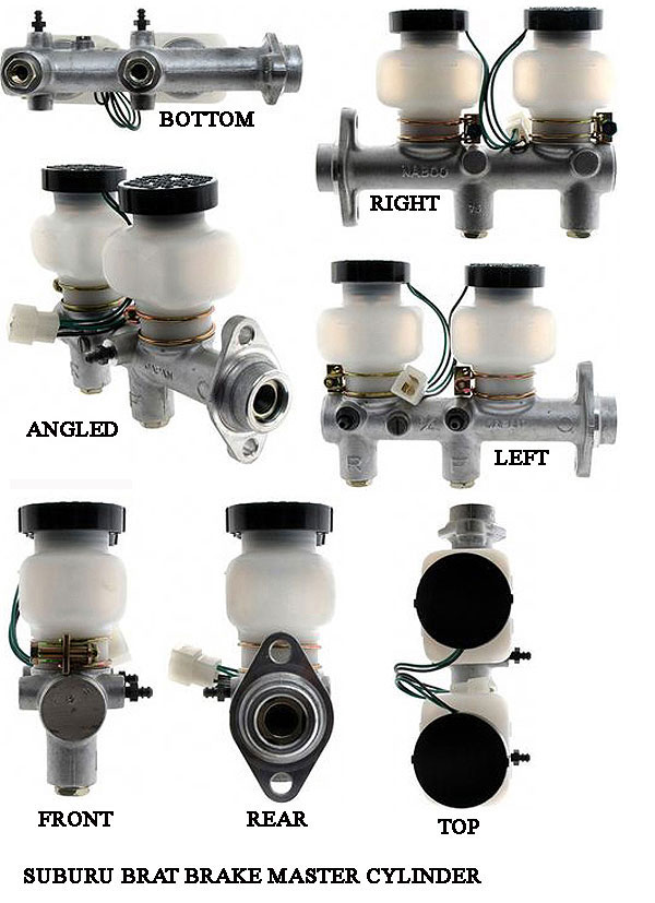 Many with
single
master cylinders have switched, for safety reason, to Dual Masters.
Sadly,
the Girling unit used by Morgan from 1978 to 1993, is no longer
available
and was very expensive when it was. One option that has been tried and
tested
by many is the one used in the Subaru "BRAT" (aka the SHIFTER in the UK
or
the BRUMBY in Australia)..but other marques also adopted it and it is
VERY hard to find now. If one is found It will require adapters and a
bit of curving of
the brake tubing and possibly relieving the entry hole into the car a
bit
but it is a close match to the Girling and much cheaper new.
Many with
single
master cylinders have switched, for safety reason, to Dual Masters.
Sadly,
the Girling unit used by Morgan from 1978 to 1993, is no longer
available
and was very expensive when it was. One option that has been tried and
tested
by many is the one used in the Subaru "BRAT" (aka the SHIFTER in the UK
or
the BRUMBY in Australia)..but other marques also adopted it and it is
VERY hard to find now. If one is found It will require adapters and a
bit of curving of
the brake tubing and possibly relieving the entry hole into the car a
bit
but it is a close match to the Girling and much cheaper new.
If anyone finds another suitable replacement, please advise me.
SUBURU BRAT MASTER
CYLINDER
by Lorne
Goldman
By the way, this SUBARU MC was used on the following cars. (12) 1978-1981
1600 (2) 1978-1979
1979 H4-1595cc
1.6L 2 BBL Vin EA71
1978 H4-1595cc
1.6L 2 BBL Vin EA71
1600 DL (2)
1978-1979
1979 H4-1595cc
1.6L 2 BBL Vin EA71
1978 H4-1595cc
1.6L 2 BBL Vin EA71
1600 FE
(1) 1979-1979
1979 H4-1595cc 1.6L
2 BBL Vin EA71
1600 GF
(2) 1978-1979
1979 H4-1595cc
1.6L 2 BBL Vin EA71
1978 H4-1595cc
1.6L 2 BBL Vin EA71
BRAT (5) 1978-1981
1981 H4-1781cc
1.8L 2 BBL Vin EA81
1980 H4-1595cc
1.6L 2 BBL Vin EA71
1980 H4-1781cc
1.8L 2 BBL Vin EA81
1979 H4-1595cc
1.6L 2 BBL Vin EA71
1978 H4-1595cc
1.6L 2 BBL Vin EA71
CROSS REFERENCE
PART NUMBERS
REPCO P8970
ACDELCO US 18M112
AIMCO M900304
RAYBESTOS MC39170
| PROPORTIONING WATCHPOINT
(1978-1993) : Savvy owners have discovered that the original Girling MC (1978-1993)
provides a 50-50 division of hydraulic force to front and rear brakes. This
is very unusual for a front disk/rear drum set up. We know of three cures.
A. One can use
a proportioning valve, (fitting it at one of the rear junctions seems easiest)
and adjust the proportion until the car is under complete control (57-60
% bias in favor of the front) or, if you are the mathematical sort,
you can use a brake bias
calculator.
B. One can use
the later AP Caparo (originally Lockheed) 1993-on Master Cylinders which
are proportioned correctly. However, these come with a booster which can
make fitting difficult as the reservoir can abut the exhaust too closely
requiring a remote reservoir.
C. Fit the Subaru
MC above which comes with proper proportioning.
The result is
a happy one. The rear brakes stop locking first making the rear end of the
car more controllable under braking. Take note, brakes are not an area
for mistakes. If you have ANY concerns, use the services of a competent professional.
That being said, even a Morgan pro not be aware of the proportioning
issue.
|
Master Cylinder Bore Size
by Lorne Goldman
The question of MC bore size has become more important as other Tandem master cylinders have being replacing the earlier (and dangerous) single cylinder brake systems Morgan used.
Decreasing MC
bore size will decrease your pedal effort and increase your pedal
travel. Conversely, a larger bore in your master cylinder will,
all other components being the same, increase your pedal effort and
decrease your pedal travel. As with some other brake parts purchases,
this comes down to your preference for how the brakes "feel" under foot
when you are driving...but Morgan owners want to retain the original
feel all while significantly increasing their safety. The magic number
is a bore size of .75" (3/4 inch)
Attaching the Brake Lines to the Master Cylinder
The ends of the NUTS
that push the flares up against the sealing surfaces in the wheel and master
cylinders are what get mushroomed out and that prevents the threads on the
nut from getting in far enough to engage the threads in the cylinders.
If you look at the nuts, the ends closest to the flared end of the brake
pipe have no threads. That portion of the nut is supposed to be smooth and
straight. That is the area that normally gets mushroomed out from over tightening.
That is the area that needs to be filed down so that its diameter is smaller
than the inside diameter of the threads. DO NOT FILE THE ACTUAL
FLARED END OF THE BRAKE LINE ITSELF. If the end of the nut is the proper
diameter and the threads on the nut and in the cylinder are in good shape,
and the nut is carefully started STRAIGHT into the threaded hole of the cylinder,
then it should screw right in with your fingers until it bottoms against the
flared end of the brake pipe. Then just snug it down with a 7/16 line wrench
and check for leakage
with pressure applied to the brake pedal.
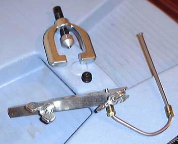
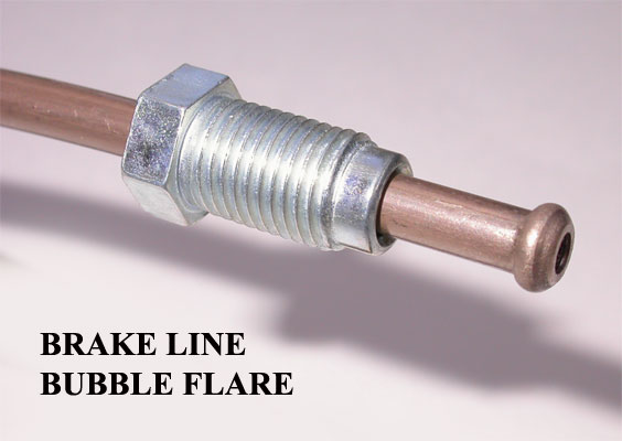
Flaring
Brake Lines
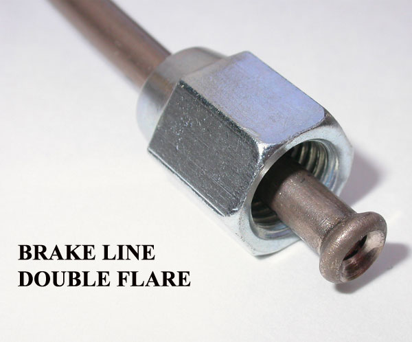 I do not recommend
single flares for brake lines. These will work acceptably for fuel lines
but are a no-no for brake lines. The safest ends for brake lines use either
a double flare or bubble flare. The problem with bubble flares are that they
are considerably harder to make perfectly for the home garagiste and for
this reason I am loathe to suggest that they be made by any other than a
professional.
I do not recommend
single flares for brake lines. These will work acceptably for fuel lines
but are a no-no for brake lines. The safest ends for brake lines use either
a double flare or bubble flare. The problem with bubble flares are that they
are considerably harder to make perfectly for the home garagiste and for
this reason I am loathe to suggest that they be made by any other than a
professional.
MAKING A DOUBLE FLARE
by Robert Robinette
 Tools: I use a
pipe cutter ($10) and a double-flare tool ($40-50) a table vice and a file.
Tools: I use a
pipe cutter ($10) and a double-flare tool ($40-50) a table vice and a file.
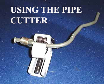
Put the pipe cutter
on the brake line where you want to cut it. Gently tighten the knob on the
cutter and then spin the cutter around the pipe about three times and then
tighten the knob a little more and repeat then repeat until the line breaks
in two. Now immediately slide on the flare nut. REMEMBER TO PUT THE FLARE
NUT ON THE PIPE BEFORE YOU FLARE IT OR YOU WILL HAVE TO CUT OFF YOUR NICE
NEW FLARE AND START OVER! Once you can slide the flare nut on the tube enough
to get a clamp on you're fine.
Now smooth out the
outer edge of the pipe with a file and use a deburring tool (or hand use
a large drill bit) to smooth out the inside edge of the pipe.
Double-flare tool
with pipe clamped, ready to flare (note both flare nuts are in place on pipe)
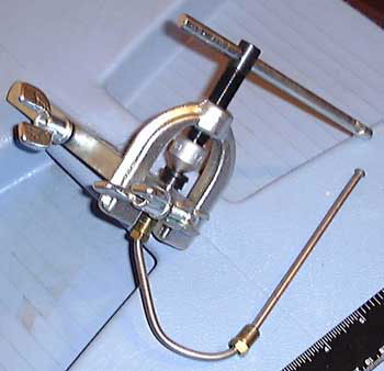
Put the flare
tool's pipe clamp on using the appropriate sized hole that matches your brake
line. Expose the required amount of pipe, clamp it down, attach the correct
adapter for the pipe you are using, screw it down on the pipe while watching
the pipe to make sure it doesn't slide out of the clamp. Now back out the
clamp and remove the adapter, then finish the double-flare by screwing down
the flare tool into the pipe. It's easier than it sounds, just follow the
directions that come with the tool. Repeat for the other brake line end.
.
Blow some WD-40 or
other solvent through your short line and then blow compressed air through
the line to dry it out. Push the brake pedal a little to flush some brake
fluid through the line coming from the master cylinder-this must be done
to remove any debris that got into the line during cutting, sanding and flaring.
Here is an explanatory
Video (If the video does not appear, please advise me)
| WATCHPOINT You must
torque the brake line nuts to 113-190 inch pounds! (about 10-15 foot pounds)
If you don't, you run the risk of having a nut coming loose and dumping brake
fluid with a loss of brake pressure and braking ability. |
Brake Lines
Brake lines are small
steel tubes often with special internal coatings to prevent rust and corrosion.
These tubes connect to the master cylinder, and then run under or at the sides of the chassis to
each of the wheels. At the wheel, a "brake hose" connects the brake line
to the caliper or wheel cylinder. As the brake pedal is pressed, the master
cylinder forces the brake fluid throughout the brake lines and into the wheel
(or brake) cylinders. This pressure causes the slave cylinder pistons to
move, forcing the shoes and pads against the drums and rotors to slow the
vehicle.
People use different
materials for brake lines. One is excellent and most others are unwise for one reasons or another.
For flexible
lines,
into the calipers and from the rigid line to the rear brake system,
I use Aeroquip, a stainless steel braded "forever" solution, the best
there is for this usage.
WATCHPOINT For the rigid lines, there is another forever product, copper/nickel product called Cunifer or Kunifer.
It is a UK invention that has swiftly gathered universal acceptance in the US and Australiaas
well.
It has all the advantages of copper but is much stronger and enduring.
GoMoG does not recommend ANYTHING else and it was recommended to
me by people a trust completely. I use it myself. Sadly, as I have
mentioned before many countries, US, Australia, the UK, often
myopically use only products and lore found locally. I
am Canadian and merely buy from any country that has the most suitable
product for the task. However, I understand we are all shaped by our
various cultures. After 30 years of dealing with Morgans all over the world, I have learned a lot.
|
 Two closely fitted
pistons are located inside the dual circuit master cylinder. The inner part
of the piston is pressed against a rubber primary cup that prevents fluid
from leaking past the piston. The outer end of the piston is pressed against
a rubber secondary cup. This prevents the fluid from getting out of the master
cylinder. The inner piston also has several little bleeder ports; these pass
through the head to the base of the primary cup. Both of the piston assemblies
are in the cylinder, and are kept there by a stop plate (or snap ring) in
the end of the cylinder. A push rod, connected to the brake linkage, applies
pressure to the pistons.
Two closely fitted
pistons are located inside the dual circuit master cylinder. The inner part
of the piston is pressed against a rubber primary cup that prevents fluid
from leaking past the piston. The outer end of the piston is pressed against
a rubber secondary cup. This prevents the fluid from getting out of the master
cylinder. The inner piston also has several little bleeder ports; these pass
through the head to the base of the primary cup. Both of the piston assemblies
are in the cylinder, and are kept there by a stop plate (or snap ring) in
the end of the cylinder. A push rod, connected to the brake linkage, applies
pressure to the pistons.
Though master cylinder
kits are sold to repair leaking cylinders and replace all the rubber components,
it is commonly accepted that the master cylinder is better completely rebuilt
with the cylinders re-shaped or replaced as new when there is a problem.
A Morgan master cylinder is normally good for 40,000 miles before a rebuild.
have the MC sleeved with stainless steel and it will become a "forever" component
requiring only rubber part replacement at long intervals.
Please note that when
replaced the Master Cylinder itself MUST be "bled" of air bubbles. This is
done with hoses attached to the cylinders brake lines and looped back into
the reservoir. By pumping the brakes, the hoses will expel bubbles into the
fluid in which the other hose ends are submerged.
Caliper Piston Seals
The caliper piston
seals are designed to keep the fluid pressure behind the pistons, and to
retract the pistons enough to allow the brake pads to just barely clear the
rotor, thus reducing rolling resistance. The seals should NEVER leak. If
a leak is detected, it must be repaired immediately, because the fluid which
escapes can defeat braking power by getting on the disc, and the pressure
loss can affect brake safety.
Brake
Hoses
The master cylinder
is connected to each wheel by brake lines and hoses. Brake hoses are specially
constructed flexible tubes with metal ends for transmitting fluid under extreme
pressure. These hoses are used to connect the calipers to the metal brake
lines, allowing the caliper to move when the wheel turns or goes up and down.
The entire hydraulic system is filled with brake fluid, which is pressurized
by the movement of the master cylinder's pistons. This fluid is very important.
Always use only the recommended fluid.
When you remove a
wheel, these hoses are easily visible. If the hoses appear cracked or brittle,
they should be replaced immediately. Close inspection of the brake hoses
is a good way to prevent catastrophe!
Brake
Fluid
Brake fluid is a special
liquid for use in hydraulic brake systems, which must meet highly exact performance
specifications. It is designed to be impervious to wide temperature changes
and to not suffer any significant changes in important physical characteristics
such as compressibility over the operating temperature range. The fluid is
designed to not boil, even when exposed to the extreme temperatures of the
brakes.
Different types of
brake fluid are used in different systems, and should NEVER be mixed. Most
cars use "DOT 3" or "DOT 4" brake fluid. Some newer cars use silicone brake
fluids. Though Dot 3 and 4 are compatible, Dot 5 should NEVER be mixed together
with either, because the seals in each car are designed to work with only
their specific fluid types. For example, the mixing of "Silicone" brake fluid
and conventional glycol based DOT 3 or DOT 4 fluids should be avoided at
all costs, as the two fluid types are not miscible (they will not mix together).
DOT 3 brake fluid and DOT 4 brake fluid CAN be mixed.
SPECIAL
NOTE ON SILICONE BASED BRAKE FLUIDS
Girling has advised
that silicone based brake fluids DO CAUSE SEAL EXPANSION.OR THE CREATION
OF A GOOEY SUBSTANCE THAT COLLECTS AROUNDS THE SEALS; In most cases, in street
driven cars this is not a problem because the hydraulic cylinder seal fits
into a groove in the piston. The groove is very deep, and the piston and
the seal slide back and forth in the bore of the cylinder in which they are
a close fit. The 10% expansion of the seal, (this is the figure used
by Girling), only makes for a tighter seal. But in some older
Girling master cylinders, the seal fits into a groove in the body of the
cylinder and the piston, which is smooth, slides back and forth through the
seal. And experience has shown that in these cylinders, the expansion
of the seal causes the seal to lose contact with the piston and the cylinder
stops working. In fact ALL pressure is lost and the pedal goes right
to the floor! The type of cylinder where this has occurred is used
in all Morgans up to about 1955. All the sealing setup
in most disc brake calipers is the same as this, therefore the use
of silicone should be restricted to clutch hydraulics and drum brake systems
that use the later design master cylinder and where the cars are driven infrequently
and are really "garage queens."
As the temp of the fluid rises, the fluid becomes more
and more compressible, and it becomes more susceptible to contributing to
a sudden, total, and unpredictable lack of any pedal pressure and consequent
brake failure. It is just not worth the risk.
If you are not
racing your car or you are a Concours competitor then silicone brake fluid
can be used. But for the reasons mentioned, it is wiser to stay away!
The other problem
(not usually mentioned) with silicone fluid is that it is much more difficult
to bleed the brakes. Pumping the pedal vigorously as one does with
glycol will cause air to dissolve into the silicone fluid and defeat the
process. One must be very gentle with the pedal action when bleeding
or use a power bleeder.
MORE
ON SILICONE FROM A GREG SOLOW EMAIL
Because we do a lot
of restoration work, I thought it would be a good idea to try silicone fluid.
We started using it for the first time about 15 years ago. What we
have found is that glycol based fluid does NOT cause Girling or Lockheed
seals to expand, silicone based fluid DO CAUSE SEAL EXPANSION.
This has been confirmed by a press release that I have from Girling that
they put out about ten years ago. In most cases, in street driven cars this
is not a problem because in most hydraulic cylinders the seal fits into a
groove in the piston, The groove is very deep, and the piston and the
seal slide back and forth in the bore of the cylinder in which they are a
close fit. The 10% expansion of the seal, (this is the figure used
by Girling), only makes for a tighter seal. But in some older Girling master
cylinders, the seal fits into a groove in the body of the cylinder
and the piston, which is smooth, slides back and forth through the seal.
In our experience, in these cylinders, the expansion of the seal causes the
seal to lose contact with the piston and the cylinder stops working. In fact
you completely lose ALL pressure and the pedal goes right to the floor!
The type of cylinder where this has occurred is used in all Morgans up to
about 1955. All the sealing setup in most disc brake calipers is the same
as this, we have decided to restrict the use of silicone fluids to
clutch hydraulics and drum brake systems that use the later design master
cylinder and where the cars are driven infrequently and are really "garage
queens."
The other cars we
use these fluids on are cars like MG T series and Morris Minors where the
master cylinder is mounted under the floor boards and are therefore exposed
to a lot of moisture as well as having the later design of cylinder.
WE DO NOT RECOMMEND
THE USE OF SILICONE FLUID FOR ANY DISC BRAKE CAR THAT IS EVER DRIVEN HARD.
As the temp of the
fluid rises, the fluid becomes more and more compressible, and it becomes
more susceptible to contributing to a sudden, total, and unpredictable lack
of any pedal pressure and consequent brake failure. It is just not worth
the risk. Regards,
Greg Solow of the ENGINE ROOMWATHCPOINT
One of the WORST things
that can happen to your car is if the brake fluid becomes contaminated, because
the seals are designed to work with only pure brake fluid. "System contamination"
means that all of the piston seals and hoses are deteriorating, and therefore
must be replaced, a MAJOR expense. So, be VERY careful what you put in the
master cylinder reservoir!
It should be noted
that brake fluid is highly corrosive to paint, and care should be used not
to get it on your car's finish.
Brake fluid will become
oxygenated over time and should be changed at intervals which are a function
of time as well as mileage.