Front Wheel
Bearings
by Lorne Goldman (updated 27 June, 2012)
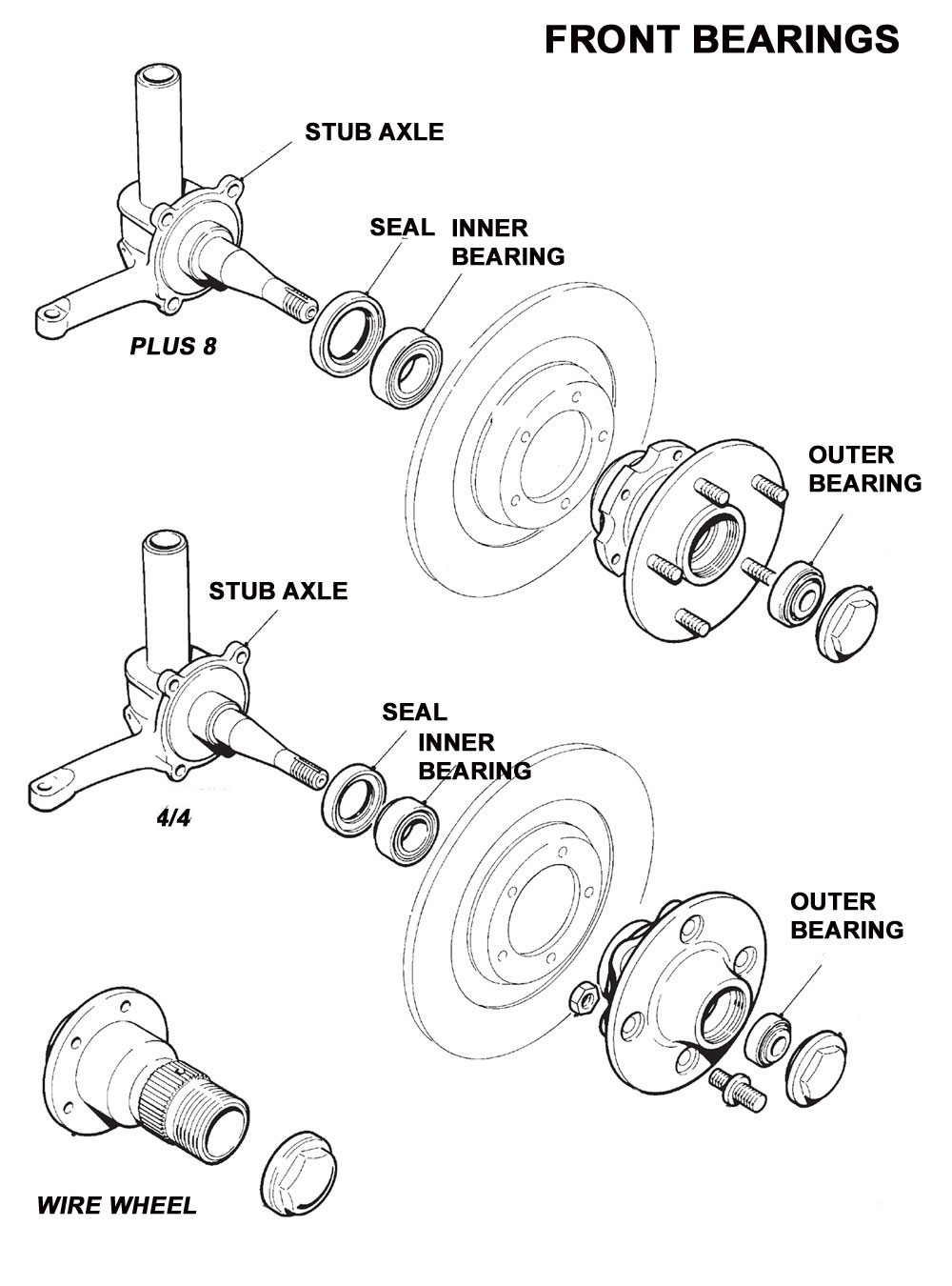
Early (Drum Brake) cars up to about SN4203, have ball
bearing front hubs with a distance piece between the two races. The outer
race of the inside bearing is held in place by a screwed ring and a castellated
nut drilled and cotter pinned in place. Failure to use such a nut may cause
loss of the wheel. Later disk brake cars have roller bearings. For instructions
on how to install them, click HERE.
Inboard: Federal
LS11
Outboard: Federal
MS7
Seal: Aeroquip 962482A or 472164
National
 Part
numbers for roller bearing cars
Part
numbers for roller bearing cars
+4 and 4/4 (5/8" Taper)
Inboard:
Inner Race (rollers/cage) Timken 1988
Outer
Race
Timken 1922
Outboard:
Inner Race (rollers/cage) Timken 03062
Outer
Race
Timken 03162
Seal: Aeroquip 962487A
Part numbers for +8 and Racing Suspension +4 (3/4"
Tap
Inboard
Inner Race (rollers/cage) Timken 14125A
Ring
Timken 14274
Outboard
Inner Race (rollers/cage) Timken 09067
Ring
Timken 09195
Seal
Aeroquip 900295A or 472164 National
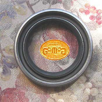
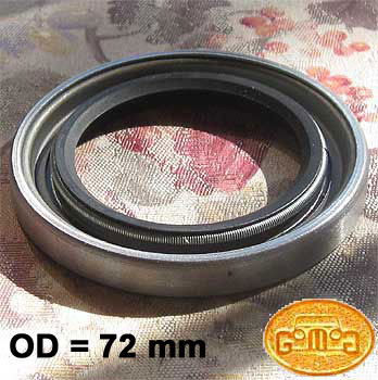
This seems to be a made-for-Morgan part. OD = 70mm, ID
(at the rubber) = 45mm and Height = 10mm See Images below
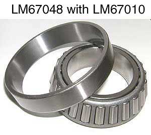
ALL CLASSICS POST-1991
Inboard
Timkins LM67048 with LM67010
Outboard
Timkins LM11949 with LM11910
Plus the strange grease seal Seal (still looking
for number!!!!)
| June 27, 2012 We sourced the part! (Thanks
to Gary Kneisley) Federal Mogul 472164.
Or Federated Auto Parts has an equal part numbered F472164 and it
notes that it replaced CR 17387. |
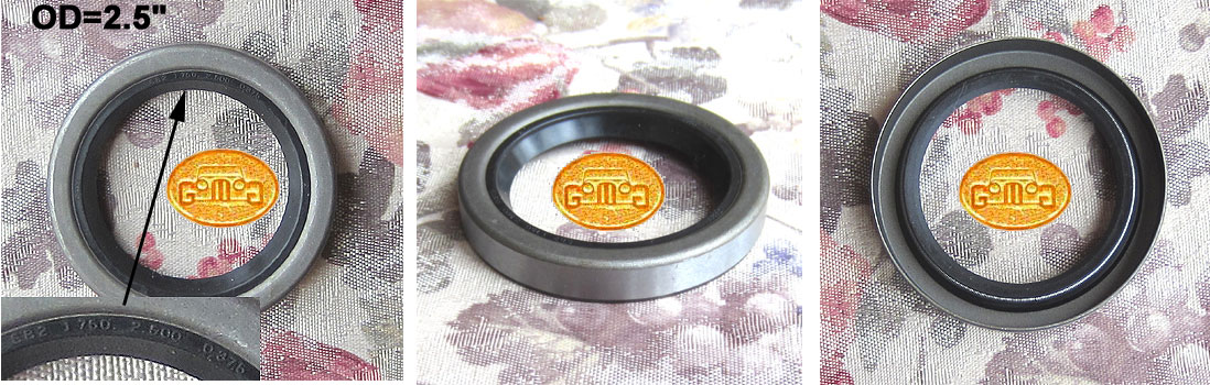
FRONT HUB GREASE SEAL
Pre-June 1993 Morgans
 |
 |
 |
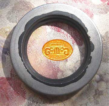
FRONT HUB GREASE SEAL
Post-June 1993 Morgans
 |
Bearing and Rotor Removal
by Lorne Goldman
On disk brake cars, the caliper will have to be removed.
The caliper is attached with two bolts (18mm), usually safety wired together.
Do
not remove the brake hose from the caliper. Hang the caliper on a coat
hanger in some out of the way place.
1. Remove the cotter key on the castle nut. On wire
wheel hubs, rotate the hub until the two holes are aligned such that the
pin can be worked out.
2. On Drum brakes, back off the adjustment
cams.
3. A 1" socket is required to loosen the castle
nut. However, the castle nut is held in place by a cotter pin. This pin
must be removed. On wire wheel cars, you will see opposite holes
in the hub placed to allow access to the pin from the side if you turn
the assembly to have them align with the pin. Now you must fiddle to get
the cotter pin out. Don't worry about breaking it. Simply replace it with
new on assembly. The removal will be a hassle, but installation is easier.
4. Slip the hub off. Ball bearing hubs
will require a puller and others may need a rubber hammer. Screw the
castle nut part way back on when breaking loose with the puller. This will
prevent the spreading of the spindle end from puller pressure.
Bearing packing and Installation
by Lorne Goldman
1. Clean the wheel bearings thoroughly and inspect them
for any signs of pitting on either balls/rollers or races. Ball bearings
can be spun (dry) while holding by the inner race at about 45 degrees from
the horizontal. You can usually feel wear (pitting) as a "grabbing" feeling.
In any event, new bearings are the wisest option.
2. Fresh bearings will not come out of the box pregreased.
So pack each thoroughly. Here
is a video. Put a generous dab of grease in the palm of your
(clean) hand and push the grease between the rollers and the cage. Do this
all around the circumference of both bearings.
3. While your hands are slathered, cup some more grease
and glob it into the disc (or drum) hub. Don't pack it full -- about 30-40
percent grease is plenty.
4. Insert the large inner bearing into the back side of
the hub. Tap the new grease seal into the back of the hub. This grease
seal is a Morgan only part.
5. Reinstall the brake disc (or drum) on the spindle,
insert the small outer bearing, and place the washer and thread on the
nut. Run the nut home, then tighten it a little more with a socket while
spinning the brake disk with the other hand. This seats the bearing further
and sets its preload. Keep spinning while tightening. You'll feel the bearing
start to bind slightly as you tighten more. Stop there.
| WATHPOINT: The earlier cars are far more sensitive to how
tight the castelnut should be torqued. Overtightening will burn their bearings
very quickly. The
later disk brake car are easier. |
6. Now back off the nut with the wrench until you feel
that resistance dissipate, and one of the castellations on the nut lines
up with the cotter pin hole.
7. Use a new cotter pin. With the earlier Don't overtighten
the spindle nut. With the Better to keep it on the looser side than make
it too tight if the cotter pin holes don't line up just right. To finish
the job, fill the dust cap halfway with grease and tap it back on. Reinstall
the brake caliper, then scrub the brake disc with brake cleaner to remove
any grease or even handprints from the friction surface.
WHEEL BEARING AND REPLACEMENT II
by Timken Bearing Manufacture
PROTECTING THE LOWER REBOUND
SPRINGS
by Stoatgobbler
Another trick is to use vacuum cleaner hose, the type
that is corrugated and compressible, this can be split and wrapped over
the lower rebound and Main springs thereby keeping some of the muck off
the "moving parts" and therefore (hopefully) reducing the production
of "grinding paste".
WEBMASTER NOTE: See the section on GAITERS.
THE PHAETON KIT (Not
recommended see Remote
Greasing [the argument against])
by Quentin English
Made by Phaeton Engineering, Hampshire (UK) PO10
7DL . It is only for Morgans.
Tel/fax +44 1243 372040
I agree with suggestions from other DG members that Factory
one shot oiler system is a 'least worse' system to cope with drivers who
can't be bothered to grease the kingpins at all. I stopped using my one
shot oiler within a thousand miles of driving my Morgan and I went over
to greasing at least every 1000 miles (preferably 500). At first
I had nipples (zirks) added to the top of the pins, but as these were difficult
to reach (particularly with my 'telescopic' grease gun taken on touring
holidays).
I have just fitted the Phaeton kit. This made by a small
outfit based in Emsworth, Hampshire,
Basically each side has a 'brake pipe' type tube. Fitting
in place of the oiler, through the inner wing valence to give an easy to
reach grease nipple/zirk. Just open the bonnet, a few strokes of
the grease gun every few hundred miles, and it should give better life
than the standard system. It is a good idea to jack the car for greasing
bottom points, and lever bottom bushes up to ensure grease gets below them.
The kit comes with a couple of ball bearings with which
to blank off the other end of the oiler pipes, but I had already sorted
these by removing one, taking the other (cut short) in a loop to the other
side. If I press the button the oil ain't going nowhere! As I said,
until recently I used a cranked nipple/zirk on the top of each king pin
- but it was a real ******* to reach (and not possible with the 'telescopic'
grease gun I use when on holiday.
It consists of 2 lengths of copper pipe, and on the end
of each pipe a grease nipple (what our 'merikan friends call a 'Zerk'.
Goodness only knows why!).
To install, jack up the front, remove the front wheels.
Drill a hole in the inner wing somewhere handy, the instructions say a
3/8th drill. The grease nipple bolts here, and the copper pipe leads to
the top of the Kingpin. Undo the existing oil-shot oiler pipe to the kingpin,
replace with the copper pipe to the
grease nipple. Inside the engine bay, undo the other
end of the oil pipes where they come from the one-shot pump. do the fittings
back up without the oil pipe, with a ball bearing in their place (supplied
in the kit), fill the new fittings with a (surprisingly large) amount of
grease. You can use chain saw oil for greasing via the Phaeton kit, it
gets in easier.
Cost (inc post) about £18 the pair.
INDEX