Morgan Kingpin Replacement
by Clark Lindsay October 2, 1989
INDEX
Background
Defintions
Needed for the Job
List of Materials
and Tools
Tear
Down Procedure - Sequence of Steps
Rebuild
Procedure - Sequence of Steps
Epilogue
BACKGROUND:
ALL
THE DEFINITIONS NEEDED FOR THE JOB
Wheel Spindle: the front axle component to which
the front wheel, brake caliper and rotor, shocks and road springs attach.
Slides up & down on the kingpin. One per front wheel.
Brake Caliper: on cars with front wheel disk brakes,
the clamshell shaped component housing the brake pads, to which the brake
line attaches. Bolts to the back of the wheel spindle. One
per front wheel. (Replaces front brake drum technology on older models)
Brake rotor: again on cars with front wheel disk
brakes, the round flat plate like device which turns with the front wheels.
Secured to the wheel spindle by the wheel bearings. Straddled by
the brake caliper, with a brake pad residing on either side of it at approximately
2:00 o'clock. One per front wheel.
Track Rod: the rod connecting the left wheel spindle
to the right spindle, and also the steering arm from the steering box.
Each end terminates in a ball joint, which will need to be separated where
it attaches to the wheel spindle.
LIST OF MATERIALS
AND TOOLS
1. Rubber gloves
2. New kingpins and brass bushings
3. Small trolley jack (borrow one if need be as
they greatly facilitate the alternatives of using a scissors
jack or worse yet, using the ½ inch threaded rod technique described
in several articles on this subject)
4. Nylon tie down strap (approx. 10 – 12 ft., available
from most auto supply stores)
5. 21 mm wrench
6. 14 mm wrench
7. 13 mm wrench
8. 11 mm wrench
9. 11/8 in socket
10 ¾ in. wrench
11. 9/16 in wrench
12 ½ in wrench
13 3/16W-1/4 BSF wrench (Whitworth)
14. Small handheld sledge hammer (steel not lead)
15. Lead knockoff hammer
16. Needle nose pliers
17. Regular pliers
18. Jack stands or blocks
19. Bearing grease
20. 2 wire coat hangers
21. 2 sandwich size baggies & twist ties
22. 12 inch pry bar (flat type used by burglars, available
at any hardware store)
23. Cue tips
TEAR
DOWN PROCEDURE - SEQUENCE OF STEPS
Make note of which parts come off which side, and replace
them accordingly.
A. Jack car up 18 inches:
Having the bottom of the frame a full 18 inches above
the ground ensures that sufficient space is available to withdraw the kingpin
out through the bottom of the lower frame member which supports the wheel
spindles. Ensure that the car is well supported on jack stands or
blocks of some sort. (I recommend both as the front of the car will
want to lift off its supports on the side being worked on, especially during
the reassembly process)
B. Remove front road wheels:
A routine operation for most owners.
C. Detach disk brake caliper from wheel spindle:
Each brake caliper is attached to the wheel spindle by
two 9/16 in. bolts that should have wire through a lateral hole in the
bolt head to ensure that they don’t come loose while motoring. Use
your pliers to untwist & remove the wire from each bolt head, remove
the bolts & slide the brake caliper off the rotor. Hang the brake
caliper from an inside fender bracket using a hook fashioned from a coat
hanger. This last step is prevents the heavy caliper from damaging
the brake hose. (The disk brake caliper and brake hoses do not need to
be disassembled during the kingpin process!)
D. Preparation to remove wheel bearings:
1. Using your needle nose pliers, straighten the cotter
pin that keeps the wheel nut from coming loose while driving. The
cotter pin & wheel nut are located inside the wheel spindle opening
(on cars with knockoff wheels). Rotate the spindle until the small
hole on each side of the spindle lines up with the cotter pin trajectory.
Remove the cotter pin by sliding it through the hole.
2. Use your 1 1/8 in. socket to remove the nut holding
the wheel bearings in place. (On cars with front drum brakes, remove
the brake drum , remove the cotter pin and undo the exposed wheel
nuts.)
3. Remove wheel bearings & disk brake rotor assembly.
Pull the disk brake rotor off the shaft by pulling the entire assembly
toward you. The outer wheel bearing & retaining washer will fall
free of the rotor assembly, the inner wheel bearing and bearing seal will
slide off with, and remain inside the rotor assembly. No tools are
needed, but it may take a sharp initial tug to dislodge the rotor assembly.
Take care not to get grease on the metal brake rotor!
4. Detach bottom of shock absorber from wheel spindle:
Undo the ¾ in nut holding the lower end of you telescopic shock
in place on the wheel spindle. Slide the lower end of the shock (&
shock bushing) off the lower shock support (part of the wheel spindle).
Leaving the shock hanging from its upper mount will speed up your reassembly
time.
E. Remove Track bar:
Remove the cotter pin & loosen the 9/16th in. nut
securing each ball joint (on the ends of the track rod) to each wheel spindle.
As crude as it seems, dislodge each end of the track bar from the wheel
spindle by giving it a series of sharp blows with your small sledge hammer.
This is a conceptually simple, but frustrating process, and I found that
a combination of hits on both the track bar (near the ends) and the ends
of the wheel spindle were necessary to complete the task. (The loosened
nut is left on the end of the ball joint thread, to ensure that you don’t
inadvertently hit and damage the bare threads)
All of the literature which I could get my hands on assured
me that this was a fast process, requiring no more than a couple of sharp
blows, which turned out not to be the case on my relatively new car.
Maybe I just couldn’t bring myself to risk demolishing the front end of
my beloved Moogie by bashing the bejesus out of it with a sledge hammer.!
The drivers side ball joint separated relatively easily, however the passenger
side proved more stubborn, and required at least 100 - 200 blows over the
course of several evenings before it separated. (By then I had panicked,
reviewed the process with anyone who would listen, including Andrew Grant
at his Cape Breton building site, Prem from Redshaw Sports Cars Repair
in Ottawa, and several times verbally consulted God and some of the others
in the good book. Contrary to his usual policy, Prem would not rent
me the requested ball joint puller. He laughed and insisted with
his usual calm demeanor that a tool was completely superfluous, and that
all I had to do was give it a few sharp whacks!! Billy Graham was
scheduled to be in Ottawa the next week, and I even thought of attending
his rally expressly for the purpose of enlisting his support.
F. Remove Oil Feed Coupling:
This is a delicate operation as the brass coupling which
screws into the top of the large bolt holding the top of the kingpin in
place rounds off very easily. Use lots of penetrating oil before
hand, and unscrew it carefully. Taking care not to bend the copper
oil tube, gently push the assembly to the side once it is removed.
The brass coupling requires a 3/16W-1/4 BSF wrench, which you if
you don’t have, you can likely borrow from a friend.
The brass coupling on the drivers side came off very easily
on my car, however I completely destroyed the fitting on the passenger
side - most frequently Nathalie’s side of the car when we go ‘toodling’.
After the episode with the passenger side track rod, I was starting to
consider that there might be a something spiritual at work here – perhaps
a supernatural bond between the passenger, and her side of the car.
However not to worry, as I subsequently determined. New brass couplings
and the accompanying acorn shaped pressure seals are readily available
from CMC in Bolton Ontario. (Don’t let my cautionary remarks deter
you from tackling this rewarding project, since as I discovered by following
the oil feed line to it’s source, if you inadvertently damage the line,
it’s standard copper brake tubing, runs from the junction block (located
on the exterior of the firewall) which feeds your oil pressure gauge, is,
and can be easily replaced.
G. Loosen Top King Pin Bolt:
Loosen, a couple of turns only, but don’t remove the 21
mm bolt holding the top of the kingpin in place. (I had to buy a 21 mm
wrench for this operation, as most metric sets skip 21 mm.)
H. Remove Round Stabilizer Rod:
Remove the 14 mm bolt securing the front of the stabilizer
rod to the wheel spindle, swing the rod out of the way towards the back
of the car, and replace the bolt in the bottom of the kingpin bottom bracket
(loosely will do).
I. Remove the Flat Damper Blade Attached to the Wheel
Spindle:
Remove the two 7/16 in. bolts connecting the flat
damper blade to the wheel spindle, and slide the damper blade out from
between the slot made on the car frame created by the shims designed specifically
for this purpose.
J. Remove Two Bolts from the Bottom of the Kingpin
Assembly:
One 7/16 in. bolt will already be loose, as it also secures
the round stabilizer rod to the bottom of the spindle assemble, and was
loosened when the rod was swung out of the way towards the back of the
car. Loosen the second bolt from the triangular plate attached to
the bottom of the kingpin, and remove both bolts.
Don’t be alarmed when the kingpin assembly drops approx.
¼ inch, it won’t drop any further until the 21 mm bolt securing
the top of the kingpin is removed (the one which we already loosened several
turns.
(Congratulations: you’ve now completed the preparatory
work, and are now ready to drop the front suspension!)
K. Jack Placement:
Place Jack snugly under king pin, using a narrow piece
of ¾ in plywood as a buffer between the metal head of
the jack and the ¾ in. nut on the bottom of the kingpin. (This
reduces the risk of the metal to metal interface slipping under pressure,
protects the lower kingpin nut from damage, and leaves sufficient room
between the jack plate and the triangular bracket on the bottom of the
kingpin to remove the two 7/16 in. retaining bolts. Loop your nylon
strap under the trolley jack and over the lower front frame member several
times, tying the ends together, to prevent the road springs from lifting
the car off the jack stands when lowering the kingpin as you lower
the jack. Completely undo the 21 mm. top king pin retaining bolt,
but leave the bolt in position in the upper frame member. Slowly
& gently lower the jack, until the kingpin assembly drops the approximately
4 inches required to take all of the pressure off the rebound spring (the
small spring below the wheel spindle).
L. Remove Front Road Spring (large, upper spring):
Remove the king pin bolt (already undone) from the upper
frame member. Firmly grip the road spring with both hands & pull
it to one side, out from under the upper frame member, until it slips free
of the frame member and extends to its full length. Don’t worry about
it hitting the inside of the front fender when extended– it’s rest position
is only 2 inches (approx.) longer than its length when compressed into
position on the front end.
M. Separating Kingpin from the Wheel Spindle:
Lift the upper road spring off the upper end of the kingpin,
slide the kingpin out via the bottom of the wheel spindle, and lift the
wheel spindle off its resting position on the lower lateral front frame
member.
The spindle is now ready to be taken to a machine shop
to have the old bushings removed and the new bushings pressed in, and honed
to the 1 in. diameter necessary to fit the kingpin.
N. Separating the Triangular Plate from the Bottom
of the Old Kingpins:
Slide the rebound spring off the kingpin and hold the
old kingpin (but never the new ones) in vice grips (or a vice if you have
one), and remove the ¾ in. nut from the bottom of each kingpin.
Webmaster note. Here is an alternate method
that may be easier for you. Click here.
REBUILD
PROCEDURE - SEQUENCE OF STEPS
For the most part, the rebuilding process is identical
to the tear down procedure in reverse. For non technical types such as
myself, the following hints & techniques will simplify the task even
further.
O. Inserting new kingpins into the wheel spindles:
Prior to inserting the new kingpins into their respective
wheel spindles, mount the bottom kingpin plate (sometimes called the kingpin
flange) and new kingpin bottom nut (comes with your new kingpins) on the
bottom of each kingpin assembly. Pack (fill) the inside of each spindle
with clean grease, place the rebound spring on the kingpins and insert
the new kingpins into the bottom of the wheel spindles. Use a Cue
tip to clean the grease out of the hole in the top of the kingpins before
proceeding any further. This hole leads to the oil channel inside
the kingpin which feeds engine oil to the outer kingpin surface, and needs
to be free of obstructions.
Prop the bottom of the kingpin with something to keep
it from sliding down and out of the wheel spindle once you’ve placed everything
in position on the car in preparation for sliding the road springs over
the top of the kingpins. (I used a small cardboard box)
P. Positioning the Upper Road Spring on the Kingpin:
Remember to slide the brass damper blade mounting bracket
over each kingpin prior to placing the road springs on the kingpins. Ensure
that the dust seals are properly re-positioned inside the top of the road
springs before the next step. Also, a bit of grease on the
rubber bushing inside the dust seal will assist with the next step.
Q. Positioning the Upper Road Spring Under the Upper
Frame Member:
Not being strong enough to muscle the upper road spring
under the upper frame member by myself, I used a flat steel metal pry bar
(approximately 12 inches long, 2 inches wide) in combination with my lead
knockoff hammer , as follows. Hooking the pry bar under the upper
frame member, and over the top of the road spring, compress the spring
to it’s approximate installed length, and use the lead hammer to tap the
spring onto position under the upper front frame member. This simple
procedure will eliminate the need for a lot of muscle power, but works
best if you have a second set of hands. My wife Nathalie assisted
me for this 2-3 minute operation.
Analogous to the tear down process, use the upper kingpin
bolt to keep the road spring positioned in place under its mounting bracket
while compressing the springs (prior to tightening the upper kingpin bolt).
Tighten it a few turns as the suspension is recompressed, but wait until
it is fully compressed to tighten it completely.
R. Compress the Kingpin in Combination with the Upper
Road Spring and Lower Rebound Spring, into Place:
Carefully raise the trolley jack (complete with wood shim,
and strapped down as for disassembly), tapping the rebound spring with
a piece of wood, if necessary, if the spring binds on the bottom of the
lower frame member as the springs compress and the kingpin rises (to its
original position).
S. Tighten the Upper Kingpin Bolts:
Tighten the upper kingpin bolts, securing the kingpins
in place. With these in place, the kingpin assembly will not dislodge,
and you can remove the trolley jack from under the assembly. Carefully
replace the brass oil feed coupling, starting it by hand so as not to strip
the soft brass coupling. Replace the bolts securing the kingpin bottom
bracket (or flange) to the ends of the front axle.
T. Reassembling Front Spring Damper Blades:
Adjust the shims (part of the damper blade assembly on
the car frame) to ensure that the assembled damper blades have no lateral
motion where they attach to the body. Also remember to clean and
grease the inboard end of the damper blades to minimize wear & tear
while mounted in the frame slot. Loose damper blades will cause front
end shimmy.
U. Remount the Brake Rotors/Front Wheel Hub Assembly:
Slide the wheel rotor assembly in place over the wheel
spindle, put some grease in between the wheel bearings, and replace the
outer wheel bearing. (You may want to repack the front wheel bearings
at this stage of the process)
V. Tightening Front Wheel Bearings:
Tighten the front wheel bearing with the wheel nut (and
retaining washer) which holds the brake rotor and the bearings in place
until a road wheel, replaced on the spindle (with the brake rotor in place)
barely moves in & out when shaken laterally. Replace the cotter
pin once the nut is sufficiently tight.
W. Remount the Brake Calipers:
Slide the brake caliper back onto its 2:00 o'clock position
over the brake rotor, tighten the bolts which secure the caliper to the
wheel spindle, and replace the locking wire with new wire (ensures the
bolts don’t loosen during driving).
X. Reconnect the Struts Attaching the Bottom of the
Kingpin Bracket to the Frame:
This is the unit that you loosened, and swung temporarily
out of the way.
Y. Reconnect the Steering Arm, Reconnect the Front
Road Shocks:
With this done, you should be ready to lower your car
from its jacked up position, and take it for a test drive.
NOW GO HAVE YOUR WHEELS PROFESSIONALLY ALIGNED.
As a word of caution, ensure that you recheck the tightness
of all fittings and bolts after your first few kilometers, and again several
times after driving longer distances (I suggest 50, 100, and again at 200
Kms.).
Z. EPILOGUE
My apologies to the pros in our midst, but this article
is written by a Morgan owning lay person, for those Morgan owners who derive
great satisfaction from performing most of their routine and periodic maintenance.
Its part of the Morgan owners philosophy, after all.
Disassembly of Front Suspension
First: Degrease the front suspension. Use a high pressure
hose. The front end becomes unbelievably greasy due to oil from the one-shot
lube, grease and road dirt. Spray brake cleaner will also do a good job.
1. Remove Shock Absorber. (See above)
Note: Steps 2 through 4 may be disregarded if the
front suspension is to be disassembled to replace the brass damper plate
only
 2.
Separate the stub axle (hub) from its track rod. Remove the cotter key
and castle nut (5/8" open end). Use a Snap-On puller
(P/N CJ89A or CJ89-3) or a Napa Puller #
SER3918 to separate. Clever people can get them off with a hammer,
but I'm not one of them.
2.
Separate the stub axle (hub) from its track rod. Remove the cotter key
and castle nut (5/8" open end). Use a Snap-On puller
(P/N CJ89A or CJ89-3) or a Napa Puller #
SER3918 to separate. Clever people can get them off with a hammer,
but I'm not one of them.
With the Snap-on, slip the puller "C" disk between the
rubber seal and spindle arm and install the puller. Screw bolt end of puller
onto the rod end bolt. Things will separate with a loud snap.
3. Remove disk brake calipers. Hang the caliper
on a wire as in hub removal. On drum brake cars the fluid line must be
broken.
4. Remove the hub (see hub removal).
5. Remove bolts (2) at the bottom of the suspension,
one also holds a stay that attaches to the chassis (1/4"-W).
6. Place a jack which is about 8" extended, under
the lower center pin retaining nut (between the bolts just removed). The
car must be at least 12" off the floor to remove the center pin.
7. Remove the one-shot lube fitting connection to
the center pin (1/4"-W).
8. Remove the center pin bolt (7/16"-W). As the
bolt is removed, the center pin will move down due to the spring force.
However, the jack will permit control of this force. After the bolt is
removed, let the jack down SLOWLY. Next, carefully jerk the upper rebound
spring out at the top. Use caution, as this spring will still be slightly
compressed. (Ed. Put an old pillow under the fender well to protect
it just in case.)
9. The upper rebound spring and the cover tube can
be removed along with the damper blade at this point.When you have all
the parts disassembled you will find major wear to the lower bush, primarily
on the inboard side (away from the hub). In very extreme cases, the stub
axle tube may also be worn. You now have to remove your old bushes and
put in new ones. PLEASE see the other articles on how to do this.
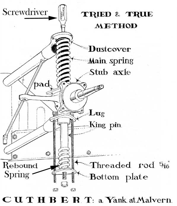
ALTERNATE METHOD (much better
for first timers!) by Cuthbert Twillie
After removing the brake caliper (you can leave it supported
on a box underneath) and the shock, detach the trackrod, the one-shot oiler
line (if you still have one) and damper plate bolts.
Now remove one of the bolts from the triangular support
plate and replace with a threaded rods about 9-12 inches long. The diameter
of the bolt hole is 5/16" and a 5/16 rod will work, but I use 1/4" rod
as it is easier. Place a nut on the top section of your rod and double
nut it (Use a second nut above it to lock the two nuts in place). Take
a third nut and thread up the bottom part of the rod until snug against
the triangular plate. Hold the top nuts witnith a small vice grip.
Then do the other bolt, double nutted, held with a vice
grip, with another nut walked up to the bottom of plate. Now remove the
large bolt the oiler tube goes into atop the king-pin. Now stick a thinnish
screwdriver into the top hole the kingpin oiler bolt came out of. This
keeps the pin and spring from popping out which is a real pucker-maker.
Now slowly loosen the bolts on both the threaded rods below, keeping them
even . Use one of the new ratcheted spanners as it faster and easier.
Assembly is the reverse of disasembly. Take care that;
1. You have correctly installed your new bushes and put
in new ones. PLEASE see the other articles on how to do this.
2. Make sure you assembly ALL components in their proper
sequence.
3. The dust cover is perfectly aligned so that it is
not crushed in assembly.
4. Before the kingpin is fully in place and there is still
some leeway for the upper bolt, thread it in the top.
INDEX