 the owners in the wrong direction
for a cure.
the owners in the wrong direction
for a cure.
Plus 8s from 1977-2004
Plus 4s (Rover versions) 1985-2000
These cars use the same bellhousing and gear shift remote...it is from
the Sd1 sedan produced from 1976-1986. Problems with the remote will appear to be gearbox issues and often send the owners in the wrong direction
for a cure.
1. RUBBER BUSHES
2. GRUB SCREW HOLDING THE GEAR LEVER
3. THE TENSIONING CUP FOR THE GEAR LEVER
4. ADJUSTING THE REMOTE BIAS
5. WHY IS MY GEARLEVER BENT??!!!
There are 3-4 minor remote (aka the shifter) problems that cause scary symptoms. They are VERY common problems. Yet they all can easily be fixed. Sadly both have often had owners and garages removing the gearbox and engine in vain only to find out later how easy it was to fix in situ.
THE REMOTE'S BUSHES
by Lorne Goldman October 2007
One problem is the flexible bushings that interface the remote's bolts into the gearbox. The early rubber ones rot and the remote becomes loose on its gearbox bolts. As one tries to shift, the remote moves on its bolts and there is a difficulty (or impossibility) to move the gear lever meaningfully as one is merely moving the remote rather than the gearbox gears.
The solution is to remove the gearbox cover (see remedial tweaks) to allow access to the remote and replace the rotten rubber bushes, ideally with the newer polyurethane ones (Land Rover Part # UKC854POLY) that last forever. The rubber ones (Rover Part # UKC854) will last a 5-20 years depending on how quickly they become contaminated by grease, usage and rot. Happily the later ones that LR adopted last forever.
In a pinch, to continue your trip, one can swap the same type rubber bushes from the sides of the remote and use washers for spacers at the sides until you find something better in an auto shop. Been there, done that.
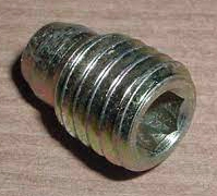
THE GRUB SCREW
by Lorne Goldman October 2007
The grub screw issue expresses itself by a progressive
(or quick) deterioration in the ability to shift. It continues until  the
driver is stuck in one gear (if they are lucky) or neutral (if they are
not) and cannot shift at all. This issue develops much faster than the bushing
problem noted above. They are unrelated save in effect.
the
driver is stuck in one gear (if they are lucky) or neutral (if they are
not) and cannot shift at all. This issue develops much faster than the bushing
problem noted above. They are unrelated save in effect.
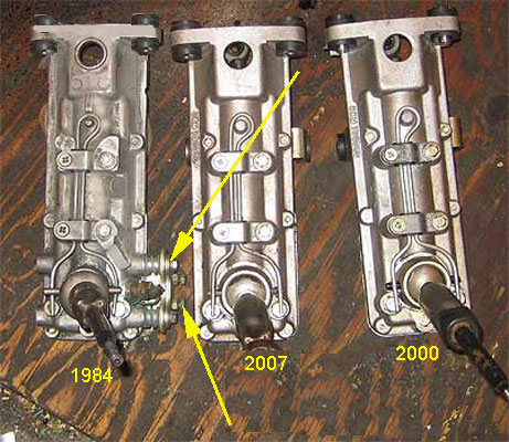
As you can seen from the diagram below, the remote has
the gear lever attached to a fitting that in turn attaches to the remote's
rod by means of a grub screw that has its point placed in an indent in the rod when it is fully screw in. This method still allows the rod to be canted but as long as the point
of the grub screw is in the indent, the rod and lever stay together.
 Sadly the grub screw is installed without
anything special to hold it in place...so they eventually loosen and
fall out. When that happens, the shift lever and the rod quickly
loosen and eventually detach, so the
Sadly the grub screw is installed without
anything special to hold it in place...so they eventually loosen and
fall out. When that happens, the shift lever and the rod quickly
loosen and eventually detach, so the 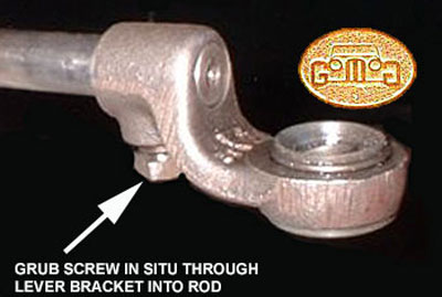 shift lever no longer has any connection to the gearbox. Keeping the grub screw in place can be done with the right Loctite (it
has for me for the last 40,000 miles on two cars) or, better still, one
can drill a small hold through the grub screw and wire it in
place. If disconnected, shifting ability is totally lost (leaving
Audrey and
I roadside in Mississippi!).
shift lever no longer has any connection to the gearbox. Keeping the grub screw in place can be done with the right Loctite (it
has for me for the last 40,000 miles on two cars) or, better still, one
can drill a small hold through the grub screw and wire it in
place. If disconnected, shifting ability is totally lost (leaving
Audrey and
I roadside in Mississippi!).
Access to the grub screw is not difficult. Remove the gearbox cover (Instructions are available if needed) and you will find a contoured plate underneath the remote at the gear lever end. It has 4 screws, remove them but hold the plate as the grub screw is most likely to be found lying at the bottom of the plate. All these plates have a hole in them to let water escape. With the later plates, these holes were made large enough to allow the screw to fall out. It is for this reason I suggest that owners of the noted Morgan Plus 8s [1977-2004] and Plus 4s [1999-2000] carry a spare grub screw in the glove box. Additionally, when replacing the grub screw, if you notice that the plate's drain hole is large enough for the screw to go through, tape it partially closed with some metal tape to prevent that. I am attaching an image of my spare remotes as an illustration.
These grub screws are not complicated but they are nowhere to be had unless made at a machine shop. I had a 25 made and sent them to other moggers when they were but my own spares are gone now. Let's see if the grub screw is the problem. If it is and it gone, we will find a way. I merely found a nearby machine shop to size them and cob up something for me on the spot. He did, I have even guided others through since. Two minutes!
Lorne
P.S. Someone may owe me a pint! (hopeful smile)
 UPDATE: (2022) I
have just be sent by a sympathetic soul, frustrated at the information
he is receiving from yet another suspect forum. :( The days of Morgan
owner acumen and owner skills are not what they used to be, though this
fellow is one after my own heart. The grub screw is being carried once
more. It is now Rover/LR Part # UYP500110 and it was once FTC4536. It is sold under both part #s at wildly different prices. UPDATE: (2022) I
have just be sent by a sympathetic soul, frustrated at the information
he is receiving from yet another suspect forum. :( The days of Morgan
owner acumen and owner skills are not what they used to be, though this
fellow is one after my own heart. The grub screw is being carried once
more. It is now Rover/LR Part # UYP500110 and it was once FTC4536. It is sold under both part #s at wildly different prices. |
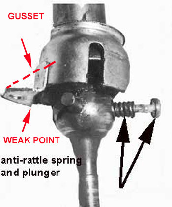
This is a very poorly little made "cup", often mistaken for only a dust cup, that holds and tensions the gear lever down against 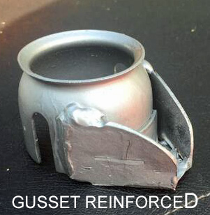 its springs. (Part # UKC3159). See the diagrams to the left & right.
Its weak point is where it little
tab (flange), used to secure it is bent by the manufacturer. When this
thin tab inevitably breaks, the shifter becomes loose and wobbly.
To repair, one must carefully remove the lever and the cup (there is a
little spring that will pop out at the rear of the ball section of the
lever..(don't lose it)
and either spot weld it or try to find another. That has become next to
impossible unless you buy an entire remote asembly from a breakup yard.
My experience with this problem happened early on so I was able to buy
a few of these cups new, but all but a single spares, which I wisely stored in the
my cars, has been given away to needy friends. Despair not, there is a
forever solution. The flange needs extra support. You can provide this
by soldering or welding in a small gusset to muchly strengthen the
weak point. This
should be done before a Morgan day is ruined, forcing you to
return home to weld the silly flange on again or it can be done,
at your leisure, in anticipation so as to avoid the problem
alltogether. (wry GoMoG smile) After 400,000 moggie kms, I have become an "anticipation" sort of
guy.
its springs. (Part # UKC3159). See the diagrams to the left & right.
Its weak point is where it little
tab (flange), used to secure it is bent by the manufacturer. When this
thin tab inevitably breaks, the shifter becomes loose and wobbly.
To repair, one must carefully remove the lever and the cup (there is a
little spring that will pop out at the rear of the ball section of the
lever..(don't lose it)
and either spot weld it or try to find another. That has become next to
impossible unless you buy an entire remote asembly from a breakup yard.
My experience with this problem happened early on so I was able to buy
a few of these cups new, but all but a single spares, which I wisely stored in the
my cars, has been given away to needy friends. Despair not, there is a
forever solution. The flange needs extra support. You can provide this
by soldering or welding in a small gusset to muchly strengthen the
weak point. This
should be done before a Morgan day is ruined, forcing you to
return home to weld the silly flange on again or it can be done,
at your leisure, in anticipation so as to avoid the problem
alltogether. (wry GoMoG smile) After 400,000 moggie kms, I have become an "anticipation" sort of
guy.
LT77 and R380 Morgan Gearbox Remote Adjustment
(PLUS 8s 1977 to 2004 and PLUS 4s 1987 to 2000)
by Lorne Goldman
 INTRODUCTION
All post-1977 Morgan models powered by a Rover engine used the LT77 gearbox and then its replacement, the R380. All of these used the Sd1 gearbox remote, which came in a few versions with minor differences. These remotes are pretty straight forward with only some WATCHPOINTS. One of these arises from the fact that the lever itself is spring-loaded. There is also a feature which prevents the lever from being accidently placed in reverse. It is adjusted to require a "slap" movement. Over time, the springs wear, and bushes wear and a bit of a re-adjustment is called for. The first sign is that reverse becomes hard to access.
Sadly, diagnosis and suggested solutions are often in error, from both amateurs and professionals. The Sd1 remote was removed from mainline production in 1987 and Land Rover R380 and LT77 remotes are different from the Sd1 version and the Morgan installation requires modifications to make sense. The clutch is often suspected and I have even seen incidents where the gearbox was unnecessarially rebuilt! Even friends will suggest that the lever be slapped harder (until damage occurs) or they suggest different angles to attack the lever. Beware!
EARLIER MODELS - Reverse
by Lorne Goldman
The Reverse Baulk Plate
Adjustment of the reverse baulk plate must be carried out on an assembled gearbox and remote.
1. Remove the bottom cover of the gear-lever remote assembly
2. Locate the gear lever in neutral in a vertical position.
3. Slacken the baulk plate adjusting bolts and locknuts
until the baulk plate is in contact with the backing plate.
4. Tighten the adjusting bolts equally until they just start to move the baulk plate out of contact with the
backing plate.
5. Adjustment should be such that an effort of 13.6 to 15.9 kgf (30 to 35 lbf) is required to overcome the
resistance of baulk plate. This can be checked using a spring balance attached to the threaded end of the gear lever (gear
knob end). Adjust be tightening or slackening the two adjacent bolts located on the right-hand side of the reverse baulk plate.
NOTE: A minimum clearance of 0.254mm (.01inch) must exist between the upper face of the baulk plate and the lower edge of the
gear-lever bush.
LATER MODELS - Reverse
by Lorne Goldman
Reverse Baulk Plate
The first adjustment is to the reverse baulk plate. Select
neutral and make sure the lever is in a vertical position. Release the
locknuts and slacken the 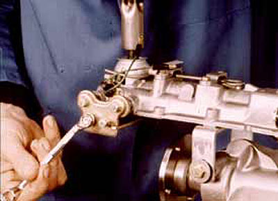 adjusting
bolts until the baulk plate just contacts the backing plate then tighten
the two bolts equally until they just start to move the baulk plate.
adjusting
bolts until the baulk plate just contacts the backing plate then tighten
the two bolts equally until they just start to move the baulk plate.
Now using a spring balance, connected to the top of the gear lever, measure the force required to move the lever to the reverse gate. Here we have fitted a nut to the lever to prevent the spring balance slipping when under tension. Adjust the two bolts to achieve the correct operating load; this is (30-35 lbf) but keep in mind, when the lever is in the neutral position, a minimum gap of 0.25mm (0.01 in) must be left between the upper face of the baulk plate and the lower edge of the gear lever bush.
1ST/2ND GATE STOP
 Next,
adjustment of the 1 st/2nd gate stop. Engage 1st gear and measure the gap
between the gear lever and the edge of the baulk plate. It should be 0.25-1.25
mm (0.01 -0.05 in). The gap is adjusted by fitting shims behind the baulk
plate spring carriers. After making an adjustment re-check the load required
to over-come the baulk plate, as reverse is selected. When all readings
are correct, fit the bottom cover.
Next,
adjustment of the 1 st/2nd gate stop. Engage 1st gear and measure the gap
between the gear lever and the edge of the baulk plate. It should be 0.25-1.25
mm (0.01 -0.05 in). The gap is adjusted by fitting shims behind the baulk
plate spring carriers. After making an adjustment re-check the load required
to over-come the baulk plate, as reverse is selected. When all readings
are correct, fit the bottom cover.
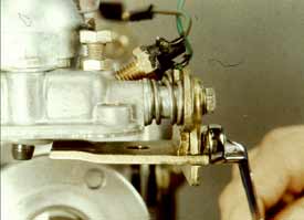
Gear Lever Bias Spring
Now the gear lever bias spring, engage third gear and
adjust the two bolts so that both spring legs are 0.5mm (0.02 in) clear
of the cross-pin. Lightly pull the lever to the left, to take up any play,
and adjust the right hand bolt downwards until the right hand spring leg
contacts the cross-pin.
Repeat the procedure on the other side, holding the lever
to the right; then select neutral and rock the lever across the gate.
The lever should return to the 3rd/4th gate when released.
The two locknuts can then be tightened.
GEAR LEVER
(why is mine bent?) Plus 8 & Rover Plus 4
by Lorne Goldman
 The
Morgan Rover-engned Plus 8s and Plus 4s used the Sd1 remote from 1977
to 2004. They were
the 2-wheel drive gearbox versions. As the stock gear lever was
too long
to clear the dashboard when pushed forward, the MMC Development
shed heated the level shafts and bent them, which only took a few
seconds. However, this not only looks silly, the consequent oblique
force applied of years, bends it all directions over time.
The
Morgan Rover-engned Plus 8s and Plus 4s used the Sd1 remote from 1977
to 2004. They were
the 2-wheel drive gearbox versions. As the stock gear lever was
too long
to clear the dashboard when pushed forward, the MMC Development
shed heated the level shafts and bent them, which only took a few
seconds. However, this not only looks silly, the consequent oblique
force applied of years, bends it all directions over time.
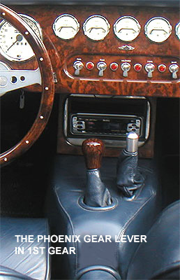
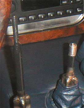
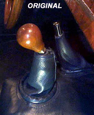
The proper cure is to cut the shaft to a length that will clear the dash. Then thread the new end and use with a shorter (hopefully more attractive) knob. This also shortens the shift throw. Above is an image of the original shifter (left) and the lever in the bent format. At the right is my cut-down version that has been straightened, threaded and and topped with a MMC-sourced burl walnut knob option with the correct shift pattern. In any event, choose your new knob before you cut and re-thread the shifter lever as you want them to match and clear the dash.
Reverse Light Switch
by Lorne Goldman
Finally, the reverse light switch, connect a battery and test lamp to the switch terminals. Select reverse, release the locknut and rotate the switch until the light just comes on; then rotate the switch 180° in a clockwise direction and tighten the locknut.
To finish the rebuild, fit the bellhousing, the clutch release bearing and support sleeve, the withdrawal lever and slipper pads and the pivot pin. The box can now be refitted to the car.
One final point, after filling the box with oil, fit a
new fibre washer to the filler plug, and tighten the plug to the correct
torque.