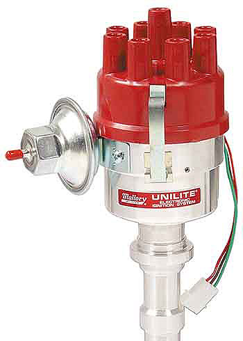
MALLORY UNILITE 4768901 without vacuum advance)
Please read the whole article. The internal links (later) are for convenience only.
As of this date,
Febrary 2026) and after constantly reviewing what's newly
out there "in the field" since, I still swear by the now
defunct Mallory Unilite
4768901 with vacuum advance. I
have not pateince with the Mallory Dual Point. Avoid them) In this, I
agree with the more honest suppliers of this engine. We are in
sync. These units come up for sale and one can still get the parts for them. Just be patient and search regulaarly.
1. Fitting a Mallory Unilite to a Plus 8
2. Recommended Wiring Setup
3. Which Mallory? DO NOT BUY A MALLORY DUAL POINT!!!
4. Ballast resistor
5. 1968 to 1977
6. 1977-2000 (or to 1998 Overseas models)
7. Removal of Old Distributor
8. Timing the Car
9. Major Watchpoint When Installing a MSD or Pertronix
A. Fix One
B. Fix Two
C. Fix Three
FITTING A MALLORY TO A PLUS 8 (without a MSD or Pertronix)
by Lorne Goldman & Win Muehling (updated July 23, 2017)
SEE ABOVE
The biggest weak point on all Rover/LR V8s until
GEMS
moved them to computer controlled distributorless ignition. (1968-2000
Plus 8s)
Rover tried one distributor design and amplifier
combo
after another. Some getting a little better and some getting a little
worse.
They were the Opus, the 35D8, the 35DE8, the 35DM8, the 35DML8. They
all
had a few vital characteristics in common,
1. the design degrades the spark from coil to plug
2. they are vulnerable to the elements and complex
to
maintain.
3. they are 2 to 3 times the price of other proper
options.
To address their issues, many solutions have been
tried.
Ignition modules like MSD, Lumenition, Micro Dynamics, or many others.
For the
distributor itself, many aftermarket
pop-in technologies
has been suggested. However, with all these solutions, the core problem
is unaddressed.
Ignition modules do not cure bad distributors and pop-in
technology does not cure bad mechanical designs.
 Mallory
began in the early in the 20th century. They supplied Ford for many
years
until Ford moved to a cheaper supplier. They produce fine
simple-to-deal-with
product based on photo optics called the Unilite. The also make other
distributors
based on other technology. When the UK racers and tuners became
frustrated
a couple of decades ago, this is where they turned to for a solution.
Carson
City, Nevada. They were available in the UK from Real Steel, Rimmer
Brothers, and John Wolfe Racing.
Mallory
began in the early in the 20th century. They supplied Ford for many
years
until Ford moved to a cheaper supplier. They produce fine
simple-to-deal-with
product based on photo optics called the Unilite. The also make other
distributors
based on other technology. When the UK racers and tuners became
frustrated
a couple of decades ago, this is where they turned to for a solution.
Carson
City, Nevada. They were available in the UK from Real Steel, Rimmer
Brothers, and John Wolfe Racing.
The greatest distributor on the planet will not
give you
more power. One cannot make a bigger explosion by using a bigger match.
However, a substandard spark can be a @#%$! nightmare. One installs a
Mallory because you are tired of fighting an unreliable component and you are
searching for an instant start-up, a good idle and no hassles at any rev range.
I have a great Mallory story involving Kevin
Vernon, the extremly talented owner of Tudor Motors up in Shropshire. Though Tudor is a century old,
Kevin has the same insatiable curiosity as our David Poole (GEMS). At the
time,he had the same set-up system on his Plus 8 as I have on mine. He had
just installed a Mallory I sent over and was wondering what all the fuss was
about. He pulled out his trusty oscilloscope and tested the spark
produced by his stock distributor side by side with the spark produced
by my Mallory. He was amazed. He had set his oscilloscope to the spark
range of his dizzy. The Mallory spark went right off the same chart!
I can recommend a Mallory Unilite for a Plus 8
with NO reservations. I have walked scores through the swap and all are happy.They are inexpensive, well made and
there is a ton of backup within the Morgan community and elsewhere.
MALLORY
DUAL POINT
N.B. I do NOT recommend the
Mallory Dual Point model for Plus 8s or Rover V8s and any car for that matter. For many reasons, they soon develop issues. However. I DO recommend that you modify it to make it into a Unilite. See my October 21, 2021 above! Inexpensive and effective.
|
| MALLORY
M.B.I. MAGNETIC BREAKERLESS OR ELECTRONIC
N.B. The external and
internal wiring of their magnetic
distributors (often called MBI for "Magnetic Breakerless" or
"Electronic" are the same as the Unilite. They are inherently less sensitive than the
Unilite..but they are also inherently less precise. They lose up to a
degree
in timing for
every 1000 rpm. Considering
that and our lack of familiarity
with them, they are not a good option. |
WHICH MALLORY DISTRIBUTOR?
There are some things you must know to order yours.
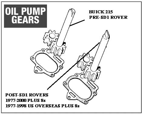
1. Distributored Rover V8s are divided into two
generations..by timing covers. The first decade of Rover production (1967-1977) used a
close copy of the Buick 215 timing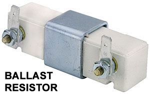 cover.
This cover had an oil pump with a female drive gear driven by a male distributor
shaft. The second generation, (1977-GEMS cars), had a better oil pump
with a male drive gear driven by a female fitting on the distributor shaft.)
You must choose your Mallory model to match your generation.
cover.
This cover had an oil pump with a female drive gear driven by a male distributor
shaft. The second generation, (1977-GEMS cars), had a better oil pump
with a male drive gear driven by a female fitting on the distributor shaft.)
You must choose your Mallory model to match your generation.
2. Mallory, like most top-flight
earlier (and later) distributors must be ballast-resisted. (The earlier Rover
already has one.) This can be done by buying a distributor ballast resistor (they are made to
a standard) from Mallory or your local car part store or buying a
Mallory internally ballast resisted coil, a red top, (which normally
gets VERY hot!). This option simplifies the wiring but these coils don't last as long. I have had my
Mallory internally ballast resisted coil crack with the heat.
(Happily I carried another in the car). Go for a external ballast
resistor. It works with any coil.
| BALLAST
RESISTORS
N.B. If the ballast
resistor terminals touch (be careful of your bonnet stays!) or is poorly grounded, the wiring will deliver a
full 12 volts to the coil and then the distributor. That will overheat
the coil and/or destroy the photo-optic heart of the Mallory. Please look here as well. |
FOR
EARLIER PLUS 8s (1968-1976) (aka Pre-Sd1)
This is the same application as the early 1960s
Buick 215. Installation is straightforward. Click INSTALLATION. Click COIL
for coil choices and WIRING.
FOR LATER DISTRIBUTORED PLUS 8s (aka
post-Sd1) = Plus 8s 1977-1996 (in the US) and 1977-2000 (everywhere else)
APRIL
23, 2018 - SINCE MALLORY WAS PUCHASED BY MSD, THIS WONDERFUL PART HAS
BEEN DISCONTINUED. The told me they would start production in a year (7 years ago). BUT!!!
all service parts for the units are still available.
The part number you need is Mallory Unilite
4768901 with vacuum advance. This Mallory Unilites comes with 24 degrees of vacuum
advance (all Mallorys have an adjustable vacuum advance feature). There are
versions ending with a "2" rather than a "1" that come with 18 degrees of vacuum
advance). The model comes without the male ending you don't want but
you will be required to swap the distributor gear and its female connection
from your existing unit to the Mallory. This is not difficult and if
you are uncertain, have a local machine shop or garage do it for you.
| WATCHPOINT:
Do NOT follow Mallory's instruction
for the gear/female connector swap CLEARANCE. It is too large and can
create
a bit of oil seepage. Use a clearance of 5 to 8 thous. |
 REMOVAL
OF THE OLD DISTRIBUTOR
REMOVAL
OF THE OLD DISTRIBUTOR
Many prefer to set the engine at TDC before doing
this
work. This is not strictly necessary but it will mitigate problems if you get anything wrong..
1. Remove the coil-to-distributor wire.
2. Remove the vacuum advance hose.
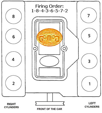
3. If you are unfamiliar with the order of the
ignition leads (the big wires from the distributor to the spark plugs) order,
mark the leads with something to identify them and take an image of the
leads still installed on the cap and the engine so that you can have the
right ignition wire on the right cap post going to the right cylinder.
Actually, you only need to know where the lead to cylinder one should be
(cylinder1 is the front right if you are standing in front of the car.). The
firing order, and therefore the order the cylinder leads are attached to the
cap is (clockwise).
4. Remove the ignition wires and the connections.
5. If there is a separate ignition module (most
Lucas
versions). remove it as well, you will not be needing it.
6. Remove
the cap and take an image of the rotor and the distributors relationship with the engine's .
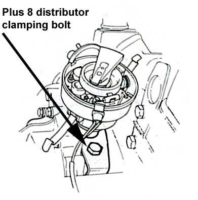
| 7. Undo the clamp holding
the distributor to the front
cover. |
 |
8. Hold the
rotor and lift upwards to
slowly remove the distributor. The rotor will turn counter-clockwise
about
15-10 degrees as the distributor lifts and it disengages the camshaft
gear.
The relationship of the rotor angle and the distributor shaft end will
become very important at re-installation.
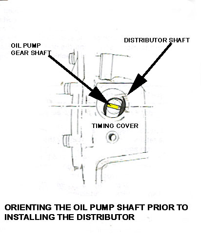
| 9.
Look down the distributor hole and
take a picture or the orientation of the oil pump drive gear. The oil
pump
drive gear must be turned on re-installation of the new distributor to
the angle that allows the rotor to arrive at the position you left it.
You will likely have to turn the oil drive gear to permit this to
happen.
This can be done with a clean screwdriver. |
|
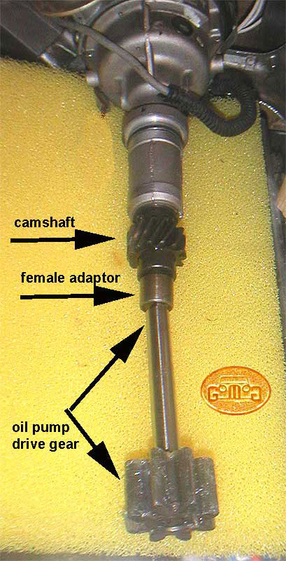
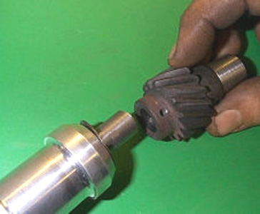
10. Now you must swap over the distributor drive
gear
and female interface fitting (along with that little washer that goes
on
the shaft between the camshaft gear and the bottom of the distributor
body.
Mallory sent a new one with the distributor.
| 11. Tap out the pin the
holds the gear and female interface
to the old distributor's shaft. Slip the washer of the shaft of the
Mallory
and then slip on the gear and its attached female fitting. |
 |
| 12. You must now drill the
shaft perfectly so that the
clearance between the gear/washer and the distributor is .005-.008
inches
(5 to 8 thous) measured by using a feeler gauge as shown at the left.
To
determine the correct bit, measure the removed pin.
This is the part that
scares most, with reason. If you
are concerned, go to a machine shop. They can do the job perfectly in a
few minutes.
|
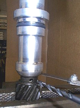 |
13. Once the hole is drilled, use a pin,
preferably a
new one, to drive into the gear and shaft holes and firmly secure the
gear
to the shaft.
INSTALLATION OF THE NEW
DISTRIBUTOR
14. (Also see "TIMING THE CAR" below.) There are
two important
things to understand for reinstallation of the distributor.
A. You want to start off with the rotor facing
very close
to the same way as it was when you took the old distributor out. This
will
only be possible if the oil pump gear the distributor shaft interfaces
with is angled to permit this. If you are too far out, the
car will
not start or back fire as your spark will be out of sync with the
engine.
When you swapped over female interface gear, it is
very
unlikely its orientation in relationship with the rotor stayed the same
as the same relationship with the old distributor. Ergo, the oil pump
gear
will often only cooperate to permit the correct final orientation of
the
rotor if you turn the oil pump gear to allow to arrive at the right
place.
Firstly, take a look at the images
you
took to see where you want;
i. the distributor aligned (using the
cap clips
or the vacuum unit as references with points in the engine).
ii. the rotor aligned, from the image you
took with the
cap off but 15-20 degrees more counterclockwise.
Click here
for why.
iii. At your workbench, hold your lightly
distributor
in your table and align the rotor and distributor to approximate the
same
relationship in the image.
iv. Now look under the distributor to see
how the slot
is angled in the female interface fitting. Compare that with how the
oil
pump gear is angled..either by looking down the distributor hole on the
engine or the image you took.
v. NOW using a long screwdriver,
turn the oil pump
gear in the engine to match the angle of the female interface on the
distributor
vi. Reinstall holding the rotor and
turning it the same
amount clockwise seen in #ii. as it engages the oil pump to seat
ENTIRELY.
| WATCHPOINT:
You are now close to starting OR
180 degrees out. If it doesn't start (with a friend turning it overhigh compression and
you fiddling at the dizzy. Remove and turn the rotor 180 and reinstall.
see
below. |
15. Reinstall the wires as indicated below.
16. Put the vacuum advance hose back on.
TIMING
THE CAR
There is some understanding necessary to timing a
4 stroke
engine. The crankshaft pushes the piston up twice for every one spark.
That has consequences.
Here are the strokes and what is happening
during each.
1. COMPRESSION stroke where the fresh air/fuel air
mixture
is compressed (all valves shut)
2. POWER stroke, starting with the spark
and resultant
combustion that pushes the piston down.
3. EXHAUST stroke, where the piston comes
back up but
with the exhaust valve open to allow the spent gases to escape.
4. INTAKE stroke when the piston goes down
sucking in
a fresh air/fuel mixture with the intake valve open.
In other words the piston is at the top, pointing
to the
same scribe, in two of the four strokes, COMPRESSION and EXHAUST. Set
the
rotor to the COMPRESSION stroke and you're fine. Set the rotor to the
EXHAUST
stroke and you are exactly 180 degrees off. Without other measures, you
have a 50-50 chance you got it right.
Frankly, for most people, that is the best way of
discovering
WHETHER they got it right. Try to start the car. If they are Piston 1
COMPRESSION
stroke's top, the car will at least attempt to start (sometimes with a
bit of adjustment. If they have it on the EXHAUST stroke, the car will
not start or may even backfire. If that happens, I simply tell them to
lift the distributor enough to disengage it and turn the rotor 180 and
re-engage it.
Of course, there are WAYS of determining the real
TDC.
But for most people I help, it is a bit beyond their skill level and
too
invasive. One way is to use your thumb to block the number 1 spark plug
hole while someone hand cranks the engine. When it is on the
COMPRESSION
stroke, you will feel compression against your thumb. (When it is on
the
EXHAUST stroke, there is no compression as the exhaust valve in that
cylinder
will be open.) When you know you are on the right stroke, you simply
have
your friend turn the crank until scribe marks say it is TDC.
The other way, surer, is to remove the valve
cover, have
a friend turn the crank until it is approaching the TDC scribe make
with
both piston 1 valves closed. (BTW, never trust Rover or LR scribe
marks.
They are inaccurate 50% of the time.)
I have found it useful to use a bit of white paint
to
mark timing points I need after I have found them. For example, one for
TDC and another for where my car likes to run on the fuel I normally
use.
This is especially important for high
compression
variants of the engine. With these engines, I have one mark for TDC,
another
mark for normal running and a last mark for running when I am traveling
and the quality of the petrol drops.
| WATCHPOINT:
Outside of great quality
workmanship on the mechanicals and its billet rather than cast body,
Mallory
Unilite magic is based solely on its optical trigger unit which is
common
to ALL Unilites for all cars and easily found. This device can be
tested
in situ in seconds roadside and replaced in minutes. If I can do it,
anyone
can do it. Outside of the USA (where the modules are available at every
auto store on every corner, carry an extra module with you. REMEMBER do not jump
start your car with the ignition
hooked up as this can kill the Unilite's ignition module. Disconnect
battery
and charge IT! or disconnect the distributor. |
WIRING
A MALLORY UNILITE FOR
A LR/ROVER V8
by Lorne Goldman
If Using an
Internally Ballast
Resisted Coil
OR
If
Using a Ballast Resistor and
Standard Coil (recommended)
If using a ballast
resister
and standard coil.
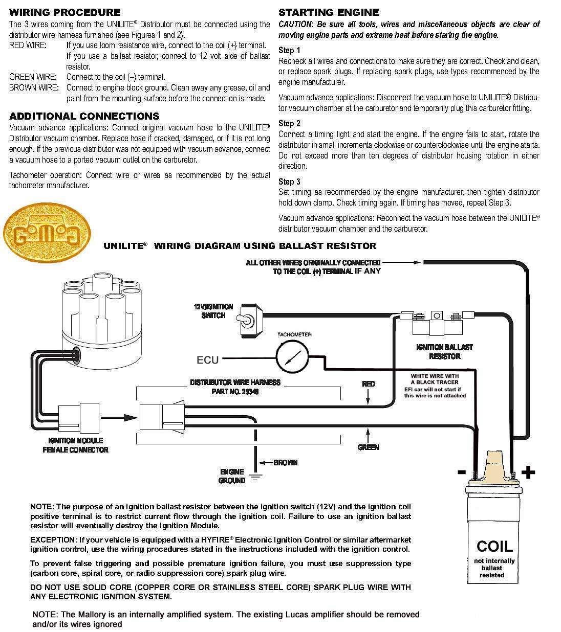
If using a internally
ballast
resisted coil (not recommended)
Major Watchpoint When Installing a MSD or Pertronix
by Lorne Goldman & Win Muehling
Like
so many other little fixes I take for granted now, I kept forgetting to
post this important watchpoint..though I have so often come across it
in the last twenty-five years and saved so many hands-on people
from despair
with it. In a nutshell, for most mid- to later Morgans (and other
 British cars)... British cars)...
In a nutshell, the British signal from the distributor to the
tach and, if you have EFI, on to the computer is of a
different format that
your car. Otherwise you would not be reading this.
So
if you fit a Morgan or other British car with either of the
titled devices, the tach won't work properly..or with EFI cars,
the car won't run.
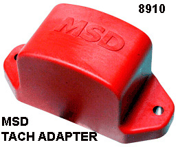
One way the problem can be solved by fitting a small device, made by MSD,
that translates the signal from the dizzy to something the British tach
and computer can understand. It is called an Tach/Fuel Injector
Adapter PN 8910 and here is the MSD documentation.
Essentially, you have to re-convert the signal (called TCV) to your newly added MSD or Pertronix to match the UK tach (and computer) again. That signal is called RVI. Read this article for more info. It is from the British side. It shows how the tach can be converted.
That
being said I have seen the necessaitity of this adapter with pre-EFI
(1984) Plus 8s. I have a 1984 L-Jetronic systems and do not need
add tach adapter.
Tach/Fuel Injection Adapter PN 8910 by MSD
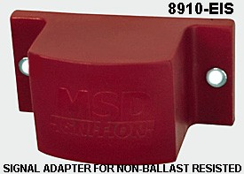
The PN 8910 (Electronic Ignition System) will interpret
the trigger signal into a signal the factory fuel injection and tachometer will recognizewhen
an MSD Ignition is installed. This adapter is designed for current limiting ignition systems
(no ballast resistor). Please
note that the adapter comes in two formats..one for ignitions with a
ballast resistor and a second for ignitions without a ballast resistor. BUY THE RIGHT ONE.
(8910-EIS).
INSTALLATION
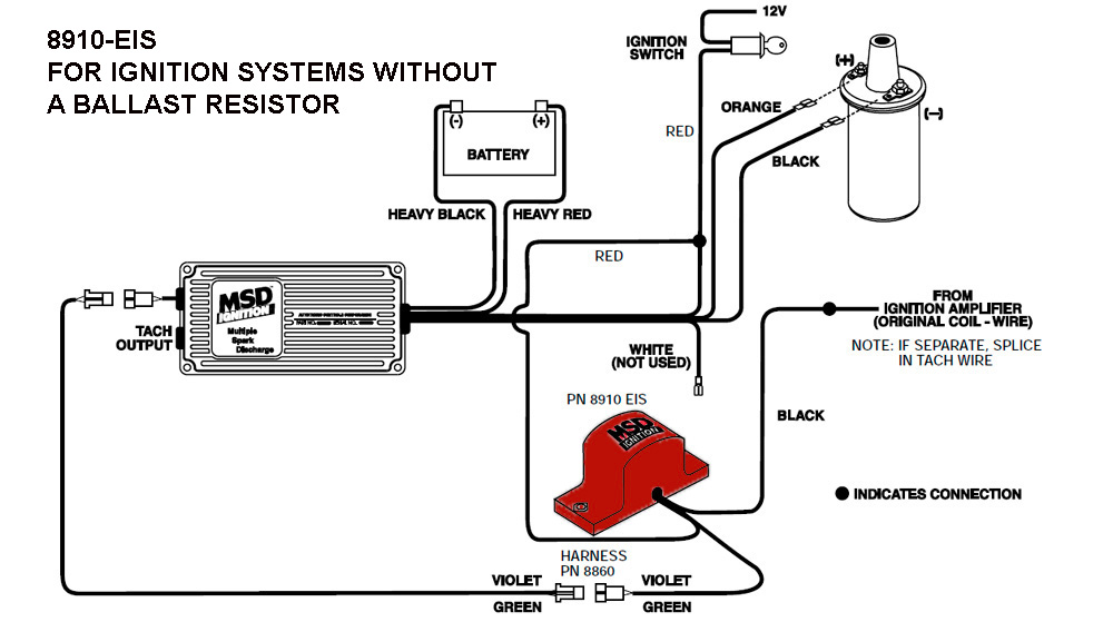 1. Mount the Tach Adapter in a location away from direct
engine heat making sure the wires reach the MSD unit and the coil. The PN 8860 Magnectic
Pickup extension harness may be used 1. Mount the Tach Adapter in a location away from direct
engine heat making sure the wires reach the MSD unit and the coil. The PN 8860 Magnectic
Pickup extension harness may be used
2. Locate the WHITE wire coming from the MSD and disconnect
it from the factory wire that it was connected to (this should be the points or ignition
amplifier wire). Seal the WHITE wire as it will not be used anymore. Leave the other MSD
wires connected.
3. Connect the BLACK wire of the PN 8910-EIS to the wire
coming from the points or ignition amplifier. (This is the same wire that the WHITE
wire of the MSD was connected to.)
4. Splice the RED wire of the PN 8910-EIS to the small RED
wire of MSD Ignition.
5. Connect the magnetic pickup connector, the GREEN AND
VIOLET wires, to the corresponding connector of the MSD.
Fix Two
FIX THREE
There is an ignition expert in California by the name of Bob
Ashlock who makes an adapter he calls TACHADAPT that would be suitable.
Cheap adapters will merely multiply whatever voltage they see, but
Bob's is regulated. Additionally, being a small operation you will have
more backup than MSD,. The MSD/Holly/Mallory service is not great.
|
Smiths Tachometer Calibration and Repair
I got interested in calibrating the Smiths electronic tachometer some time
ago when I realized that my tach was completely out of calibration. I used a
technique similar to the one described in Tom Ballous 1975 Tech Tip to calibrate
my tach at about 1200RPM using my dwell/tach meter. I began to wonder, however,
how well calibrated my dwell/tach meter was and how well my Smiths tach was
at high RPM. This curiosity led me to analyze how the Smiths tach works and
to design a personal computer based tach calibration tool. This paper is intended
to explain how the tachometer works, to explain how my tach calibrator works,
and to update Tom Ballous Tech Tip with my opinions and advice.
Tachometer background information:
I know of two types of electronic tachometers in cars, inductively coupled
and direct coupled.
Direct connect electronic tachs have a direct electrical connection to the
ignition circuit. These tachs use voltage signals in the ignition circuit to
drive the tach.
The inductively coupled type of tach such as the Smiths electronic tachs of
the 1960s uses a one turn loop of the ignition wire as the primary side of a
transformer that couples the current pulses caused by the cars ignition circuit
into the inside of the tach. The timing of those current pulses are used to
drive the tach. These tachometers were used in Sunbeam Tigers and Alpines as
well as in Shelby Cobras and other British cars of the period. Since this is
the tach Ive had the most experience with, this is the tach I will describe
in detail.
The Smiths tach must be disassembled in order to calibrate or repair it. Carefully
rotate the chrome bezel until the tabs on the bezel line up with the slots on
the case. This can be a very difficult job if the seals have aged badly and
stuck. Whatever you do, DON'T pry up the tabs on the bezel or youll ruin it.
If you need to, you can CAREFULLY pry a tiny bit around the bezel in an attempt
to break it loose. Don't tap the edge as the meter is very fragile.
Once you get the chrome bezel off the tach, the face glass and inside bezel
must come out, if they didn't come out with the chrome bezel. Carefully pry
the inner bezel from the case. It is not necessary to separate the glass from
either bezel if it is stuck to one of them. Be careful prying on anything, especially
if the glass is still in place, as it is very easy to damage it or the bezels.
I have not been able to locate a source for the seals, so I just try to be very
careful, and reuse what I can with whats left of the seals. I always use a lint
free cloth and glass cleaner to clean the glass while the tach is apart.
Once the meter face is exposed, be very careful not to mar or get finger prints
on the face or break the needle. The next step is to remove the tach innards
from the case.
There are four screws on the back of the case, two of which are recessed in
holes in the case and two of which are not. The two in the recessed holes hold
the innards of the tach together so don't take them out. Put the tach case face
down on the bench. While pinching the U bracket stud with one finger and the
power spade lug with another to hold up the tach innards, remove both of the
non-recessed screws. The tach innards are now being held in the case by your
two fingers. Pick up the case and cup your other hand under the face of the
case. Carefully let the stud and spade lug slide out of your fingers and catch
the face of the tach by the edges in the cup of your hand. You can then pull
the case off of the tach innards and turn it over. You are now ready to calibrate
or debug the tach.
This is a good time to slide a shield under the needle to shield the face and
repaint the needle if you can find appropriate paint. (My artistic talents arent
very good, so I never try that step myself.)
Reassembly is the reverse of this process.
Electronically, the Smiths tach is a relatively simple two Germanium transistor
inductively coupled electronic tach.
Two transistors together form a monostable multivibrator, or one-shot.
Normally, the collector of Q1 is at 6V. An ignition pulse couples through the
transformer to trigger a one-shot voltage pulse to 12V on the collector of Q1
for a set amount of time. Every time an ignition pulse is detected through the
transformer, the collector of Q1 will pulse from 6V to 12V for a fixed amount
of time. While the collector of Q1 is at 12V, the top of the meter is held at
6V by the Zener diode, so current will flow through the meter, causing the needle
to deflect. The width of the voltage pulse is determined by the combination
of the 0.25uF capacitor C2 and the combination of resistors R3, R4 and pot.
R5. The one-shot is triggered by every ignition pulse, so the voltage waveform
looks like a series of pulses when the engine is running. Since the pulses are
fixed in width and the frequency of the pulses is determined by the engine speed,
the ratio of the time the waveform is at 12V vs. 6V goes up with increases in
engine speed and down with decreases in engine speed. The way the meter works,
the more time the waveform is at 12V, the more the needle is deflected and the
less time the waveform is at 12V, the less the needle is deflected.

As the meter movements wear, lose their lubrication or get dirty, they require
more energy to deflect the meter. On many older tachs, I have found that
widening the one shot pulse width works to add the required energy. However,
the one shot pulse will be terminated early if the ignition pulse gets shorter
than the one shot pulse. I have found that many older tachs can't be adjusted
enough to compensate for the required extra energy. The symptom of this
problem is a tach that will not register above a certain RPM. I have tried
sewing machine oil to improve the meter movement as recommended by my jeweler,
but to no avail. Untill I am able to identify a lubricant or a cleaner/lubricant
combination that works, I add energy by cutting down on the resistance of the
55 ohm resistor/thermistor combination.
To calibrate the meter, you want to drive the tach with a very accurate, known
signal at the correct frequency for the RPM reading that you want on the meter.
Once you are driving the tach with the accurate frequency, you can adjust the
needle deflection to the proper place by turning the calibration pot. R5. The
tach can only be calibrated at one RPM. After that, all you can do is check
to see how close you are at other RPMs.
It is possible to recalibrate the 7,000RPM Alpine 4 cylinder tachs to work
in V8 Tigers using this method.
These tachometers contain electronic parts that are about 30 years old. The
characteristics of all the internal components are likely to slowly change as
they age, and I have found a number of tachs that have become uncalibrated,
and many fail.
The most common failure modes I have seen are failure of the main timing capacitor
C2. Failure of this cap. has caused tachs to be erratic, temperature sensitive
or just plain dead. If you suspect your tach to have this problem, locate the
capacitor, carefully unsolder the capacitor, and replace it with a new one.
I have been occasionally able to locate a supply of 0.25uF capacitors, but available
0.22uF to 0.27uF capacitors work fine. I also come across numeraous tachs with
a failed transistor input transistor. The symptom of that failure is that
the tach will not work in cars with lower ignition current. One way to
diagnose this problem is to temporarily pull the plastic block off tha back
of the tach, move the wire a bit and put two or three loops of wire through
the metal "U" bracket that goes over the plastic block and put that
on the back of the tach. If the added magnetic flux gives you enough signal
to trigger the tach, then the input transistor is failing. This could
also be an indication of problem with your coil circuit as well, however.
The other major failure mechanism I have seen is a broken meter spring. The
meter needs to be replaced in this case. Replacement meters must be gotten from
a parts tach. As a matter of course, the tach will have to be recalibrated if
any of the parts are replaced. I use an ohm meter to test for meter
movemement continuity. A good meter movement will give a reading of about
70 ohms in our out of the circuit, iwth the ohmneter positive to the red wire
and negative to the black.
All of the broken meter movements I have seen exhibit an open circuit.
All of the Smiths tachs of this era use the same electronic and mechanical
design, regardless of number of cylinders, positive or negative ground or the
make of the car. The power and ground wires are reversed between tachs for positive
or negative ground cars. The only other thing that changes is the face used
on the meters. So don't throw away any vintage Smiths tachs or tach parts, even
if they are dead. They can be used to resurrect any other one.
Calibration:
After learning how the Smiths tach works, I set about to develop a highly accurate
personal computer based calibration tool, as I didnt trust any other dwell/tach
meter any more than I did my Smiths. The calibration tool I designed is conceptually
quite simple. I designed a unit that plugs into the serial port of an Intel
compatible personal computer and will generate a current pulse through the ignition
wire that simulates the current pulse that happens when a spark plug is fired.
I then wrote a program that causes the current pulses to occur at very precise
times based on the RPM desired by the user. The timing is based on the highly
accurate crystal used for timing on the computers serial port. This crystal
controlled circuit must be highly accurate, or computers would not be able to
communicate with one another. This device and software will convert your personal
computer into a highly accurate tach calibrator that works from 500 to 10,000RPM,
in the car or on the bench.
For the curious, I found that my 1200RPM dwell/tach meter was over 100 RPM
off at 1200 RPM and my tach was off about 1000RPM at 5000RPM even after my dwell/tach
calibration effort.
Here are the three Youtube videos he published regarding his conversion:
I especially wouldn't calibrate my tach at high RPM using Tom's method, since
the risk to the engine is not necessary anymore.
It is not often obvious by external inspection if the 0.25uF cap has failed.
If the tach is not functional or temperature sensitive, it is the first thing
I would replace to see if that is the problem.
The germanium transistors used in the Smiths design have a very low threshold
voltage. Silicon transistors have a much higher threshold voltage. It is likely
that replacing the germanium transistors with silicon transistors could really
change the characteristics of the tach. However, I would stick with the germanium
transistors. The HEP 253 number is still a good number for finding a germanium
replacement, although they are hard to find. You sure can't get them from Radio
Shack any more. There are some small electronics distributors who still do carry
them. Another good part number is NTE158.
You can live with more turns of the ignition wire through the metal loop, which
will give you a higher flux density for coupling the ignition signal to the
tach. However, I wouldn't do it unless absolutely necessary, as removal of the
nylon block on the ignition wire makes me worry about chafing the insulation
off the ignition wire, shorting 12V to the tach and stalling the car, if not
causing an electrical fire. I'd replace the input transistor if you have
this situation.
To Obtain a Tach Calibrator:
In order to allow Sunbeam enthusiasts to accurately calibrate their tachs,
I have started manufacturing the PC peripheral calibration units plus software
for sale.
The calibrator consists of a unit that amplifies a signal coming out of the
computer's serial port so it will emulate the ignition current pulses of your
car. There is also PC software that drives the serial port to produce
highly accurate timing pulses. This, in conjunction with an external
power supply (such as your car's battery) allows you to debug tach problems
and c451015502711737 calibrate funtional tachs.