Most of the older Morgan instruments can be accurately recalibrated right in your own garage. Does your amp gauge read slightly discharged when your actually charging? Does your radiator boil over at 50C.? Have you ever said you can't be out of gas when your gas gauge reads half full? And the topper of them all: What is my oil pressure? Well, for those of you who are avid gauge readers, like myself, here is the way to get back your confidence in them.
This whole recalibration process started as just another everyday Saturday tinkering session on my 52 flat grille. The gas gauge has never worked since I bought my car. I proceeded to extract the gas tank and found my gas float sunk at the bottom. I removed the sending unit with the float and repaired the float by soldering after draining it. Next, having felt I cured my gauge's problem, I re-installed the tank and switched on the ignition; Rats! Same old problemdoesn't WORK! After checking for broken or faulty wires, 1 decided the problem was in the gauge itself. After removing the gauge from the dash I carefully disassembled it. Inside there are two coils. An empty register coil and a full register coil. By manipulating these those coils along with raising or lowering the float your gas gauge needle will soon be covering the entire range. I left mine so that when the needle rests on the empty peg I still have a two gallon reserve.
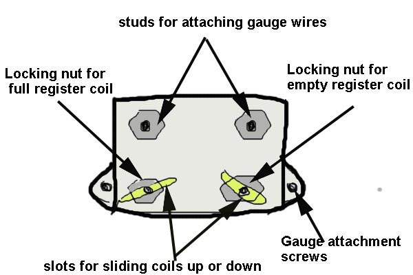
This is what your gas gauge looks like from the back,
I disassembled my gauge to understand how it works. You don't have to do this because the following adjustments are made exactly the way the gauge sits in the instrument housing. Also, before proceeding with the calibration, if your gauge doesn't work at all make sure there is not an internal broken wire in the gauge or in the sending unit by use ohmmeter or other device.
In this procedure you must use a hook made, from a clothes hanger to hook the float rod so you may bring it to the top of the tank. When the float is held in the top position, the full coil nut should be loosened and slightly moved higher or lower in its slot. When the needle is in its full register tighten the coil nut just enough to hold it in place. Next, remove the hook from the float and lower it into the empty position. Repeat the above instruction with the empty coil this time. When the empty coil has been locked in place check the gauge readout by raising and lowering the float (all this and the coil adjusting must be carried out with the ignition on!). If at any time while slowly raising or lowering the float the needle jumps to full or empty after passing the half way mark, the coil on the side the needle jumps to is adjusted too close to the needle. Readjust and test until correct. When completed, tighten the coil nuts snug and recheck the gauge to make sure the coils didn't shift during this final tightening. This completes the calibration off this gauge.
1966 +4 GAUGE II
by Vern Dale-Johnson
If it is similar to later Lucas gauges, (my 66 +4 is being used as a reference) you can adjust the gauge. On the back, besides the two electrical posts, are two small posts in slots. Very carefully loosen one nut just enough so you can move the post in the slot - do not twist the post! Moving the post changes the relationship of the internal magnet to the armature on the gauge needle. By carefully playing with both posts you'll be able to set your gauge so it reads "empty" when empty (or better yet when it is about 1/4 full) and full when full.
You may find it easiest to remove the gauge from the car, understand how the adjustments work, then reinstall and fiddle with it.
Addendum by Duncan Charlton
One nut adjusts the location of the center of the range of the needle sweep and the other adjusts the width of range of sweep of the needle. Sometimes you can get an accurate reading at one end of the scale, but not have enough range or too much range, meaning that while E is accurate, 1/4 might be at the F end of the scale.
You can try adding a few resistors to the circuit to improve the range but on this car you can never really get a realistic reading in the full range unless you replace the float unit with the type of sending unit that reads resistance between a wire and its surrounding housing tube.
If you pull out the float unit and lay it on a piece of stiff cardboard, you can trace the position of the arm at different fuel depths (the float probably does not displace much fuel, so you can figure on the fuel level being right about where the lowest part of the float is at a given point in its range). If you keep it connected to the gauge you can see the how the readings correspond with the position of the arm. It is possible to modify the position of the needle to some degree by bending the float arm enough to change the position of the wiper on the rheostat in the sending unit at any given fuel level setting. Take note of the unavoidable phenomenon with your current set up: when the tank is 3/4 full, the float is nearly touching the top of the tank (ours was 8" deep). Therefore, adding a small amount of fuel to this level will cause the float to hit the top of the tank, and the needle will no longer move to indicate the higher level because the float can't rise any further.
If I fill the tank, I usually know it's full -- I don't need the gauge to tell me this, and I'm likely to remember that I fuelled up recently. But given the obvious inconvenience of running out of fuel, I chose to make the gauge accurate from 1/2 full to empty, with the E mark about one and a half to two gallons above true empty.
If you are brave enough to fiddle with those nuts on the back of the gauge, remove the gauge from the panel first but connect it to the sending unit (take it out of the tank) to see where the needle needs to be set.Those nuts are on a post that goes through the middle of a wound post. You don't want to rotate that post, so if you can take the gauge out of the cluster you can better see to avoid rotating the post and breaking the delicate wire that winds around it.
I can't recall which post does what, but start by moving one post 1/8 of an inch or less to see what the effect is. Changing the setting of one post affects the other, so this will take a few tries to get satisfactory results. I was happy with the results on mine. The needle would not go much above 3/4 full, which pretty closely corresponded to the position of the float arm when at 3/4 or more.
You can do the whole job on a workbench if you have a 12 volt power supply and note what connects to what.
A couple of people asked for the details on calibrating the old, differential magnet-type fuel gauges. Here is what I did when calibrating a friend's gauge for his MGA. I checked the results on my three Jaguar gauges so I am pretty sure that it is correct.
Go to Radio Shack or some other electronic's store and pick up a sleeve of five 15 Ohm resistors and an alligator clip. Go home and solder them together in series and attach the gator clip to one end. If you can, it is nice to have a short wire with a connector attached to the two fuel gauge leads. This will reduce the chance of shorting everything out.
I used a battery charger for a 12 volt supply- polarity
doesn't seem to matter. Hook the 12 volts to the gauge input and
the case. Hook the gator clamp on the resistors to the case as well-
my gauges have two
mounting tangs that make this easy.
The gauge will swing hard past full with the sender wire open and empty with it grounded. On the sender, full gives about 70 ohms resistance to ground so just work down the resistor array from the end to the gator clip for 75, 60, 45, 30, 15, and 0 Ohms to ground. 45 and thirty should bracket the half full mark with the others near the quarter marks.
If your gauge does this, you are done. To adjust, ground the sender wire then loosen the nut on one of the two magnet cores- doesn't really matter which one. Move the core back and forth until the needle points at empty or just below empty- you don't want it above empty or else you will have a false sense of security. Then move to the other end of the resistor array and adjust the other magnet until the gauge points at full or just past full. This is an iterative process. Once you are satisfied with the endpoints, check the middle points again to see if they make sense then install and enjoy!
I think the resistors I bought were one-half Watt 1% resistors but I expect the 1/4 Watt 5% resistors would work as well. The sleeve of five resistors was 99 cents at the mall. I bought them while my eldest daughter was doing whatever 14 year old girls do in malls when they know their parents may be watching.
If this is unclear, I can try again. Once you have the parts in front of you, it will make a lot more sense.
Bill Eastman
Bill!
Very good method for adjusting the fuel gauge but with all that Ohm, resistors, and one-half Watt 1% stuff your Jaguar breeding is showing. ( Hell this is Morgan, We talk angle iron and hammers :)
A method that I have used, and I'm sure will work for other electrically challenged owners is as follows:
Remove the sending unit from the tank. Place the mounting plate of the sending unit on the top edge of a piece of poster board. Measure the depth of the tank at the mounting hole and mark it off from the top of the poster board, which is 11 inches if I remember correctly. Now the 11 inch line is the bottom of the tank and the top of the poster board is the top. Since all the sides of the Morgan gas tankare perpendicular to each other (ie basically a box) 5 1/2 inches up from the 11 inch line is halve a tank. Place the float on the top o the 51/2 inch line and the gauge should read 1/2 . You can then adjust the magnets to read correctly.
A WARNING : the wire windings of the magnets is very very fine wire and if the magnet nut is loosened too much the magnet can turn and break the wire. Be careful to loosen the nut only enough to slide the magnet . You can see a piece of plastic (or something) that is fitted to the slot to keep the magnet from turning. If you loosen up the nut more than the thickness of the metal casing the magnet can turn.
Bob Nogueira
Your oil gauge can easily be calibrated by connecting an accurate oil gauge into the system via the flexible oil line coming from the oil filter assembly and leading to the front suspension lubricating switch. Once the gauge has been inserted let your engine warm up completely, especially if you are using a multi-viscosity oil since this oil thickens as the temperature rises and so causes slightly higher pressure in the process. Observe and record the pressure at idle and also at around 2000 rpms. When done remove the gauge and reconnect the flex oil line thus placing your dash gauge back into operation. Now, start your engine again and repeat the above procedure recording what your dash gauge reads. To adjust the dash gauge you must remove the chrome ring, glass gasket and instrument divider plate in the instrument housing. This is accomplished by loosening the holding bracket nuts at the rear and slowly rotating the chrome ring until the tabs inside release through slots around the inside of the housing. Once all this is removed the fronts and needles of all the gauges will be exposed. To calibrate, you must very carefully hold the bottom of the needle gently bend the top of it to the direction desired for either a higher or lower reading. After bending, restart the engine and check your pressure. If it is correct with the accurate pressure recorded earlier, your done, if not you must repeat the needle bending until successful. When done calibrating you can then adjust (if necessary) your engine oil pressure via the adjusting screw on the filter assembly.
While the front of the instrument housing is off the amperage gauge can also be adjusted in similar manner. Leaving the ignition off and all other electrical apparatus, check to see if the needle is centered. If not, bend it just like the oil gauge needle until it stays in the center or the 0 position on the calibrated scale.
TEMPERATURE GAUGE
The Repair of the Morgan +4 Temperature Gauge
by Bob Nogueira nogera2@worldnet.att.net
The Smiths made temperature gauge is used in the Plus 4 (4 in 1 gauge cluster). While not unique to Morgan, it is extremely rare and parts (sender units) are no longer available. To date I have not found an alternative sender unit that can be substituted for the original. Below is outlined the procedure for replacing all the working parts of the Morgan gauge with that of the Smiths TR6 Temperature gauge. When finished there is no visible difference in the appearance of the Morgan Temperature Gauge .
The criteria for a donor gauge were as follows:
1. The needle should point up rather than down
(so that it will read correctly on the Smiths face)
2, the needle range of travel should be the same as the
Smiths (many gauges have a much greater span)
3. The donor should fit in the limited space of the 4
in 1 cluster.
After studying many gauges I found that the Smiths gauge used on the Triumph TR6 and GT6 of 1973 and up meet all the above criteria. I also found that new parts (senders) were still available and used gauges were plentiful. I purchased a gauge and sender on E-Bay for 15.00. Note: While I can not say first hand, this would appear to be the same type modification that Morgan Spares uses to restore this temperature gauge)
General Overview:
This is not a difficult procedure however given the small
parts and delicate needle I would suggest that it 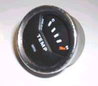 be
done in a clean well-lit location and that you not rush.
be
done in a clean well-lit location and that you not rush.
Parts needed:
1 One Triumph TR6 (GT6) temperature gauge
2. One Triumph TR6 (GT6) sender unit
3. Four Spade type wire ends
4. Two fibre washers 1/4 outside diameter
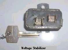 5.
One Voltage stabilizer (MGB or TR6)
5.
One Voltage stabilizer (MGB or TR6)
(Note: The Voltage stabilizer is a small box, which
is fitted between the 12 v power source and the gauge. It reduces the voltage
from 12 volts (more or less) to a constant 10 volts. This allow the gauge
to read consistently regardless of the battery condition or generator output.
Morgan's failure to use this devise may account for the high reading of
the Morgan temperature gauge.
Disassembly of the Smiths 4 in 1 Temperature Gauge
1. Pull the 4 in 1 from the dash panel
2. Disconnect the two wires to the Temp gauge, the mounting
screw and bracket stud holding the unit to the cluster (HINT:
mark the top of the gauge, as when it is stripped it can be difficult to
tell the top from the bottom of the case
3. Remove the faceplate from the gauge by drilling the
mounting holes with a drill bit, which is slightly over size. (Be
careful to not bend the needle when handling the gauge or removing the
faceplate)
4. Remove the needle from the gauge. The needle is held
in place by fitting on the spring and bimetal bar. Pressing on the spring
will allow the needle to be slipped off the mount. CAREFULLY examine how
it is fitted and installation will be easy. (Note if you are squeamish
and don't mind the TR6 needle on your gauge,
you can skip this step)
5. Remove the two nuts and plastic blocks on the wire
posts on the back of the housing
6. Drill or grind off the mounting rivets for the
bi-metal bar and spring
All the internal parts of the gauge should now lift out.
Disassembly of the TR6 Gauge
7. Remove the bezel, glass, light shield and face plate.
8. Remove the two nuts on the wire posts
9. Unlike the 4 in 1 gauge all the internal parts of
the
TR-6 Gauge are all mounted to a fibre board (photo) and
held in the case only by the two mounting posts. You will now note that
the shape of this fibreboard is the same as the 4-in-1 temperature
gauge housing (kidney shaped)
The Transplant
10. The TR 6 fibreboard is a perfect fit into the 4 in 1 housing with the exception of one of the wire mounting posts. Modify the 4 in1 by drilling a 1/4 hole for the post in the housing . You should also drill out the other post hole to this size. (photo) Hint: the best way to locate the hole in the correct location is to cut the mounting post and light tube off the back of the old TR-6 case. Place the 4 in 1 and TR-6 cases back to back with the one hole matched up.
Mark where the centre of the second hole is located on the back of the 4 in 1. You will also note another hole, which is an access hole to adjust the spring. You should also mark and drill out this hole if you want to fine-tune the gauge readings.
11. Cut a piece of gasket paper to cover the back of the inside of the 4 in 1 housing and punch holes for the posts and adjustment access holes. The post holes should be the same Dia (5/32) as the posts not the case holes
12 With the gasket paper in place insert the TR 6 fibre board into the 4 in 1 housing (This is where having marked the 'top' comes in handy).
13. Place the 1/4 fibre washers on the posts. If they do not fit flush with the case back use a round file to enlarge the hole where needed until the washer fits flush. Next place the notched fibre washers which were originally on the TR6 gauge and the nuts on to the posts and. tighten. Insure the two mounting posts are isolated from the case by the two fibre washers on each post.
14. Remove the needle and replace it with the 4 in 1 needle.
15 Replace the faceplate. Use a small dab of hot glue
or silicone seal to hold it in place.
(Note: what ever you use needs to only hold
the face plate in place until it is mounted so don't over do it)
16. Remount the temp gauge to the 4 in 1 cluster gauge. (Note the TR6 posts can accept the round wire ends found on the Morgan but it is tight fit. I used the TR spades and replaced the Morgan's round wire ends with spade ends.
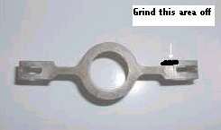 17.
The bracket which holds the 4 in 1 cluster to the dash will foul
one of the posts on the back of the mounted gauge and could short out the
gauge . Correct this by grinding a notch in the bracket to clear the post
(photo). As an additional precaution I placed a rubber tube over the post
after the wire is attached
17.
The bracket which holds the 4 in 1 cluster to the dash will foul
one of the posts on the back of the mounted gauge and could short out the
gauge . Correct this by grinding a notch in the bracket to clear the post
(photo). As an additional precaution I placed a rubber tube over the post
after the wire is attached
18. Mount the voltage stabilizer to the under side of the dash so that the case is grounded (the stabilizer must be grounded to work properly) The power lead (solid green) should go to the stabilizer and a jumper wire from the Stabilizer to the gauge. The sender wire (green/black) should go directly to the gauge. (Hint: The gauge does not care which post gets the power wire)
19. Replace the sender unit in the radiator with the TR-6 sender unit. The threads are the same size however the Morgan's round wire terminal will need to be replaced with a spade terminal)
Optional: Calibrating the Gauge
Just about every Plus 4 owner I have ever talked to relate
that the original temperature gauge reads hot.
This may be a result of Morgan not using a voltage stabilizer
or a gauge that is simply out of adjustment.
The following apply to both the original gauges and your
TR6 'Transplanted' Gauge.
1. Remove the sender unit from the radiator and suspend it in a pan of water. Clip a grounding lead from the sender to the car
2. With a thermometer in the water, heat the water to 180 F.
3. Place a small screwdriver in the adjusting slot on the back of the gauge and turn to move the needle to the centre of the Normal block.
4. Raise the temperature and once the water starts boiling, the needle should be at the bottom of the hot block . My Gauge reads as follows Bottom of normal = 170 F Top of normal = 190 F Bottom of Hot = 212 F
This article is the copyright of the Morgan Motorcar Club of Texas and may be reprinted without permission for non-profit purposes only.
ATTENTION TR2, TR3, TR4 owners and racers.
I just had a car towed to my shop with a failed oil pump
gear. The oil pump gears that have been supplied by TRF and by Moss
USA appear to be made by the same people. The 4 lobed inner gear
rotor is pinned to the shaft that drives it with a steel pin that appears
the same as the originals that were
produced by Holbourn Eaton ( I believe). On the
pump that we inspected today, the pin had worked its way out of the rotor
until it jammed against the outer rotor, siezing the pump and shearing
the drive shaft that comes down from the distributor drive gear.
This gear had been in service for 9,000 miles over a period of 3 years.
There were no signs of anything that could have possiblly caused
this failure. The pin appears to have worked itself loose on its own.
(Unfortunately, the owner didn't shut the engine down in time even though
he heard "knocking " noises and he drove the engine until it spun the rod
bearings and siezed). According to Moss the warrantee on the oil pump gears
is "one year, unlimited milage".
As these are the only pump gears available at this time, so far as I know, I am very concerned as it could be a major problem. As of yet, I don't know how big. I am going to check all of the gears I have in stock and try to press the pin out. I don't know how tight a press it should be . I will compress it to some original but worn out gears that I still have around.
Regards, Greg Solow
The Engine Room
Santa Cruz, Ca.