TACHOMETER REPLACEMENT
by George Dow April 2017
PROBLEM SYMPTOMS
While churning over my 1985/6 +8 on the starter motor after a period of lay up I noticed the (electronic) rev counter took a pulse that caused the needle to deflect up the scale and drop back to sit at 2500RPM! The engine had not fired up at the time.
 When the engine did fire up the needle rose from 2500 RPM with the rise
in engine revs, thus was responding to changes in revs though giving a
new and false higher reading. On switching the ignition off the needle
dropped to zero and when the ignition was switched back on with the
engine now stopped, the rev counter needle returned to 2500 RPM! At
any time thereafter as soon as the ignition was switched ON the rev
counter needle would rise immediately to read 2500RPM. If the starter
was engaged and the engine fired up the needle would rise from
2500RPM?
When the engine did fire up the needle rose from 2500 RPM with the rise
in engine revs, thus was responding to changes in revs though giving a
new and false higher reading. On switching the ignition off the needle
dropped to zero and when the ignition was switched back on with the
engine now stopped, the rev counter needle returned to 2500 RPM! At
any time thereafter as soon as the ignition was switched ON the rev
counter needle would rise immediately to read 2500RPM. If the starter
was engaged and the engine fired up the needle would rise from
2500RPM?
ANALYSIS
At the time I did not want to take the instrument apart in the off chance I might damage it beyond possible repair, and did not want to send it off for repair lest it get lost in the post or any similar issue that may leave me with a hole in the dashboard. Thus it seemed wise to try to buy a replacement, which when I contacted a Morgan specific dealer, I was told that my year of +8`s instrument was no longer available as new though could offer a repair service... SO back to possible postal issues!
On searching the web I came across a Welsh company by the name of Speedy Cables. After further search on their service, and found there were a few complaints as to the lack of speed in their business practic. However, found them to be speedy enough they answered my email in four days (Fri-Mon) and I took delivery of my replacement newTachometer on the following Friday.
Speedy Cables listed a chrome rimmed Tachometer in the size and with a very similar face to that of my tachometer. Hopwever, their return email assured me they could fit a matte black rim similar to my originalt. Job done £134.84 +vat and postage. Well...er... not quite job done. Read on. NOTE When ordering, you should note to Speedy what color your internal illumination is..
While I was delighted to find a new replacement that looked identical other than a few words of small print along the bottom edge of my original instrument identifying it as being an 8CYL and line of text denoting its country of origin, etc. none of which mattered a jot to me. The new instrument itself is a more up to date design than the original and requires it to be setup in order to operate correctly as well as care taken in connecting it up to the Morgan`s electrical system, lest you damage the instrument's internals.
But there is nothing difficult in the processes required if you can crimp a few terminals to make connection between the old and new.
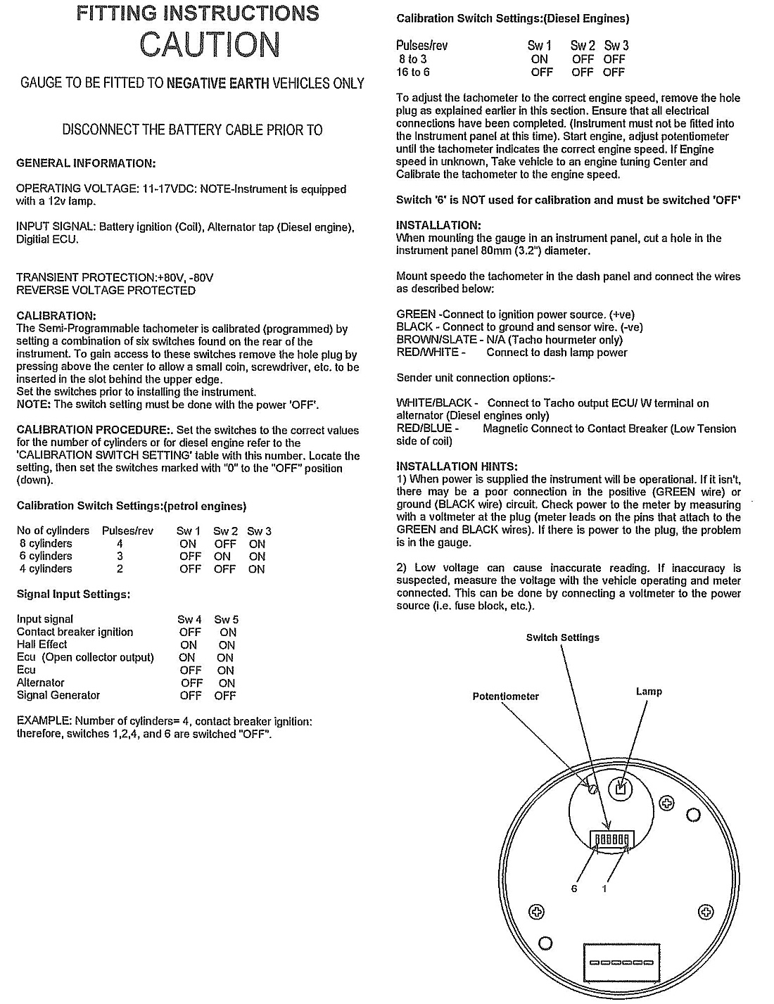
SETUP PROCEDURE: READ THEIR INSTRUCTIONS.... the tables printed therein seem far more complex at first glance than they turn out to be.
 The new tachometer is a negative earth/ground device as was the old one
so no issue there though it`s internal circuitry is different and
The new tachometer is a negative earth/ground device as was the old one
so no issue there though it`s internal circuitry is different and 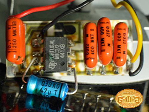 like
many digital electronic devices has to be set-up to give the appropriate
OUTPUT relative to the INPUT it receives, given this new instrument is
capable of taking input from any one of a multitude of electrical
devices to give a read out in RPM.
like
many digital electronic devices has to be set-up to give the appropriate
OUTPUT relative to the INPUT it receives, given this new instrument is
capable of taking input from any one of a multitude of electrical
devices to give a read out in RPM.
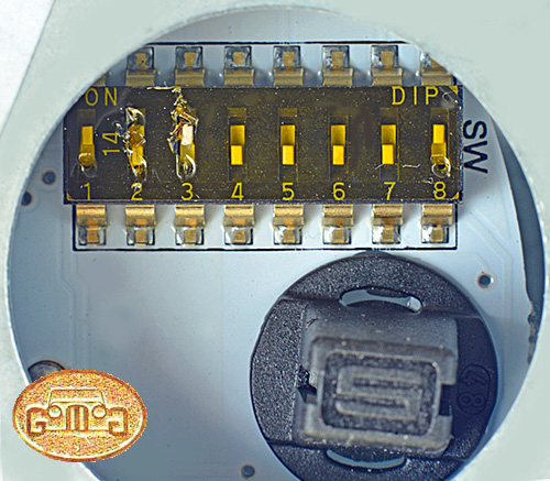
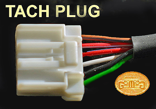
From the images, it can be seen that there are physical differences though none that matter relative to the way it looks when in place in the dash. On the rear of the instrument there is a round black rubber grommet which provides access to the little light-bulb holder for instrument illumination (more on that later). More importantly it provides access to a tiny series of eight "dip" switches contained in a block which must be individually switched into a specific position (either ON or OFF) to match the car's input to the instrument. It sounds complex but is not, all that is required is something the size of a tooth pic or very small screwdriver to flip the switches to their required position.
The image of the dip switches (left) will hopefully help simplify understanding. ON is also marked on the left hand side of the block in order that a switch can be clearly seen to be switched to either off or on regardless of the angle such a block may be mounted on a circuit board.
My 8-cylinder fires 4 times for each revolution of the crank so, from the provided tables, I placed the switches as instructed which, in my case, was a simple operation requiring only two of the switch positions to be altered from the way they were set when I received the instrumen. Switch 1 and switch 2 arrived in the ON position which was correct for a 4 cylinder input. Also switch 8 was ON, which seems to be a requirement for the majority of inputs, as it is in the case of both 4 and 8 cylinder engines. The chnages required to switch the instrumnets from a 4 to a 8 cylinder engine was merely to switch # 2 to OFF and switch # 3 to ON.
INSTALLATION
Only after the dip switches have been set should you think about connecting the instrument to the vehicles wiring and only then (according to the instructions) with the NEGATIVE strap disconnected from the battery.
To wire it in, you can either cut off the existing Lucar/spade terminals and replace them with your choice of straight through connectors. Or you can solder the connections, or as I did, you can make off the ends of the wired plug supplied with the instrument with crimp on MALE Lucar connectors that will then plug into the existing connections. Of course you need to take care as the number and colours of wires supplied with the new instrument do not exactly match those used in the existing installation, though the instructions contain the necessary connections information.
CONNECTIONS - 4
There are four connections (though the pre wired plug has 6 wires, two of which are unnecessary. I just bent the unneded two round and tucked the ends into the sleeving around the plug wiring. _
Illumination: The internal illumination of the instrument is supplied, as the original was, with the RED wire the WHITE tracer.
Signal from the Coil: This signal is normally fed through the WHITE wire the BLACK tracer. You can see it attached at its other end to the coil. However, it seems the preference here (from the Carerbont instructions) is to use the RED/BLUE in the plug wiring for the signal, which I did. WEBMASTER NOTE: Beware here. On EFI cars the same white wire with a black tracer feeds the tachometer and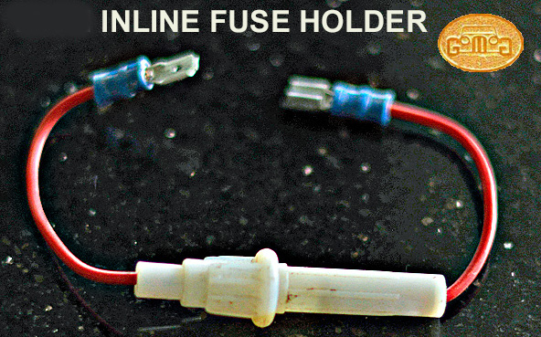 then on
from the tachometer to the ECU, giving it a vital signal. Without this
wire connected to the ECU, the car will not start or run.
then on
from the tachometer to the ECU, giving it a vital signal. Without this
wire connected to the ECU, the car will not start or run.
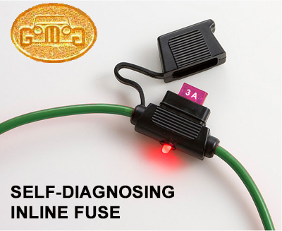
The green in the wiring loom can be connected to the green in the plug wiring and supplies the power to the instrument when the ignition is switched on. Please note the instructions suggest that the green supply wire should be fused at 3 Amps, apparently to protect the device electronics from any power more than that. I considered it advisable to fit an in line accessory fuse (image on the left) between the green of the Morgan`s wiring (excuse my red wires for the fuse holder) and that of the tach's plug. Use a 3 amp fuse. Fuse holders can come with any fuse type you wish. Match the fuse with the type your car already uses. These inline fuses also come with Lucar connectors already crimped in place, one male and one female as in the image, though be sure to have no bare metal showing when the connection is made... There are female connectors that have insulating sleeves over them. WEBMASTER: In such spots, where future access is a bit of a pain, I now use blade fuses in self-diagnosing holders. They only cost a 1-2£ more and allow trouble checking at a glance.
EARTH/GROUND The last wire to connect is the earth/ground which for both the instrument and the Morgan`s wiring loom is BLACK so no complication there. NOTE the case of the instrument does not require earthing as the illumination circuit is now internal to the instrument thus the original bulb and holder are no longer required though the red/white from the existing bulb is used as above to supply the feed to the light in the new instrument.
 ILLUMINATION: One other little issue which may be of no consequence to some is that
the original instrument was illuminated in green, whereas the
replacement is lit in white.
ILLUMINATION: One other little issue which may be of no consequence to some is that
the original instrument was illuminated in green, whereas the
replacement is lit in white.
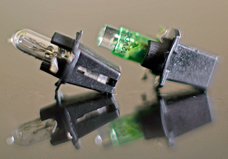
On contacting SpeedyCables again, they supplied me with a replacement lamp holder with an integral green LED (Light Emitting Diode) unlike the filament lamp originally supplied. With the replacement LED fitted the new Tachometer matched now my Speedometer`s colour when the lights were switched on... NOTE: It is IMPORTANT to remember that LED`s are polarity dependant thus if the LED does not light up after fitting it is best to remove it and replace it in the hole 180 degrees round from your first attempt and in doing so you will have reversed the polarity of the connections to the LED.
RESULTS: In my case all worked well enough though on checking with my timing light the gauge seemed to be reading perhaps 50RPM over though whether that was down to the timing light read out innacuracy or not..? As I am not racing My Morgan to it`s limits and a.. POSSIBLE.. 50RPM discrepancy is not a big deal for me.... if it exists at all.
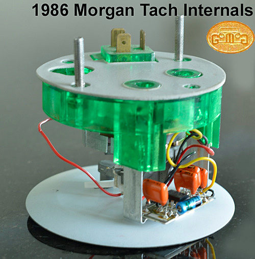
THE ORIGINAL UNIT: Now that I have a working Tachometer I had the confidence to open up my faulty instrument though found nothing obvious within, and while I had it opened I took the opportunity to photograph the internals in the hope that those with the skills and access to electronic components might find interest. On a far more basic level, from the image of the internals of my original instrument you may notice the use of translucent green plastic as part of it`s internal framework, as part of that framework also provides the means of holding the original lamp holder to the rear of the instrument and in doing so filters the instrument illumination to provide the green illumination that was seen as white until the green LED was fitted.
Should you have occasion to strip an original instrument I would suggest that you remove the two Philips/cross head screws on the back of the case...No need to remove those recessed in the green plastic also visible on the rear of the case. Remove the two small nuts at the base of the long threaded screws that are used to hold the instrument to the rear of the dashboard. there are two tiny nylon washers under those nuts which should also be removed as they grip the threads tightly and would restrict removal of the instrument internals. Once the fixings have been removed it seems wise to then turn your attention to prising up the tabs holding the rim to instrument case. I found these to be quite resistant to bending though used a small sharp screwdriver successfully. Note that the tabs do not need to be bent till they are straight as there is enough flexibility in the rim to enable the tabs to be eased over the edge of the instrument case individually.
Try not to touch the face or the inside of the glass.
The face of the instrument is somewhat recessed so the whole device can be placed face down on a clean stable area in a bid to apply pressure to remove the internal structure as one piece, which in the case of my instrument was not as simple as expected. There is a foam backing fixed to the rear of the green plastic internal framework and in the case of my instrument this had adhered to the bottom of the instrument casing. It would be easy to damage the long threads of the screws while applying pressure to them though if you screw the large alloy thumb screws flush with the tops of the threads then that will provide a larger area on which to apply pressure, I also applied pressure to the green plastic area at the connections and working between those areas finally encouraged enough loosemovement in the internal structure to the extent it could then be removed.
by George Dow April 2017
PROBLEM SYMPTOMS
While churning over my 1985/6 +8 on the starter motor after a period of lay up I noticed the (electronic) rev counter took a pulse that caused the needle to deflect up the scale and drop back to sit at 2500RPM! The engine had not fired up at the time.
When the engine did fire up the needle rose from 2500 RPM with the rise
in engine revs, thus was responding to changes in revs though giving a
new and false higher reading. On switching the ignition off the needle
dropped to zero and when the ignition was switched back on with the
engine now stopped, the rev counter needle returned to 2500 RPM! At
any time thereafter as soon as the ignition was switched ON the rev
counter needle would rise immediately to read 2500RPM. If the starter
was engaged and the engine fired up the needle would rise from
2500RPM?
ANALYSIS
At the time I did not want to take the instrument apart in the off chance I might damage it beyond possible repair, and did not want to send it off for repair lest it get lost in the post or any similar issue that may leave me with a hole in the dashboard. Thus it seemed wise to try to buy a replacement, which when I contacted a Morgan specific dealer, I was told that my year of +8`s instrument was no longer available as new though could offer a repair service... SO back to possible postal issues!
| SpeedyCables is a division of Caerbont Automotive Instruments Ltd (CAI), an independent company in South Wales engaged in the design and manufacture of car instruments, instrument clusters, senders, electronic control and interface modules and wiring harnesses for the specialist automotive and industrial markets. They are an important supplier to Morgan and other noted automobile and marine manufacturers. They supply the Smiths lineup as well. |
On searching the web I came across a Welsh company by the name of Speedy Cables. After further search on their service, and found there were a few complaints as to the lack of speed in their business practic. However, found them to be speedy enough they answered my email in four days (Fri-Mon) and I took delivery of my replacement newTachometer on the following Friday.
Speedy Cables listed a chrome rimmed Tachometer in the size and with a very similar face to that of my tachometer. Hopwever, their return email assured me they could fit a matte black rim similar to my originalt. Job done £134.84 +vat and postage. Well...er... not quite job done. Read on. NOTE When ordering, you should note to Speedy what color your internal illumination is..
While I was delighted to find a new replacement that looked identical other than a few words of small print along the bottom edge of my original instrument identifying it as being an 8CYL and line of text denoting its country of origin, etc. none of which mattered a jot to me. The new instrument itself is a more up to date design than the original and requires it to be setup in order to operate correctly as well as care taken in connecting it up to the Morgan`s electrical system, lest you damage the instrument's internals.
But there is nothing difficult in the processes required if you can crimp a few terminals to make connection between the old and new.
SETUP PROCEDURE: READ THEIR INSTRUCTIONS.... the tables printed therein seem far more complex at first glance than they turn out to be.
The new tachometer is a negative earth/ground device as was the old one
so no issue there though it`s internal circuitry is different and like
many digital electronic devices has to be set-up to give the appropriate
OUTPUT relative to the INPUT it receives, given this new instrument is
capable of taking input from any one of a multitude of electrical
devices to give a read out in RPM.
From the images, it can be seen that there are physical differences though none that matter relative to the way it looks when in place in the dash. On the rear of the instrument there is a round black rubber grommet which provides access to the little light-bulb holder for instrument illumination (more on that later). More importantly it provides access to a tiny series of eight "dip" switches contained in a block which must be individually switched into a specific position (either ON or OFF) to match the car's input to the instrument. It sounds complex but is not, all that is required is something the size of a tooth pic or very small screwdriver to flip the switches to their required position.
The image of the dip switches (left) will hopefully help simplify understanding. ON is also marked on the left hand side of the block in order that a switch can be clearly seen to be switched to either off or on regardless of the angle such a block may be mounted on a circuit board.
My 8-cylinder fires 4 times for each revolution of the crank so, from the provided tables, I placed the switches as instructed which, in my case, was a simple operation requiring only two of the switch positions to be altered from the way they were set when I received the instrumen. Switch 1 and switch 2 arrived in the ON position which was correct for a 4 cylinder input. Also switch 8 was ON, which seems to be a requirement for the majority of inputs, as it is in the case of both 4 and 8 cylinder engines. The chnages required to switch the instrumnets from a 4 to a 8 cylinder engine was merely to switch # 2 to OFF and switch # 3 to ON.
INSTALLATION
Only after the dip switches have been set should you think about connecting the instrument to the vehicles wiring and only then (according to the instructions) with the NEGATIVE strap disconnected from the battery.
To wire it in, you can either cut off the existing Lucar/spade terminals and replace them with your choice of straight through connectors. Or you can solder the connections, or as I did, you can make off the ends of the wired plug supplied with the instrument with crimp on MALE Lucar connectors that will then plug into the existing connections. Of course you need to take care as the number and colours of wires supplied with the new instrument do not exactly match those used in the existing installation, though the instructions contain the necessary connections information.
CONNECTIONS - 4
There are four connections (though the pre wired plug has 6 wires, two of which are unnecessary. I just bent the unneded two round and tucked the ends into the sleeving around the plug wiring. _
Illumination: The internal illumination of the instrument is supplied, as the original was, with the RED wire the WHITE tracer.
Signal from the Coil: This signal is normally fed through the WHITE wire the BLACK tracer. You can see it attached at its other end to the coil. However, it seems the preference here (from the Carerbont instructions) is to use the RED/BLUE in the plug wiring for the signal, which I did. WEBMASTER NOTE: Beware here. On EFI cars the same white wire with a black tracer feeds the tachometer and
then on
from the tachometer to the ECU, giving it a vital signal. Without this
wire connected to the ECU, the car will not start or run. The green in the wiring loom can be connected to the green in the plug wiring and supplies the power to the instrument when the ignition is switched on. Please note the instructions suggest that the green supply wire should be fused at 3 Amps, apparently to protect the device electronics from any power more than that. I considered it advisable to fit an in line accessory fuse (image on the left) between the green of the Morgan`s wiring (excuse my red wires for the fuse holder) and that of the tach's plug. Use a 3 amp fuse. Fuse holders can come with any fuse type you wish. Match the fuse with the type your car already uses. These inline fuses also come with Lucar connectors already crimped in place, one male and one female as in the image, though be sure to have no bare metal showing when the connection is made... There are female connectors that have insulating sleeves over them. WEBMASTER: In such spots, where future access is a bit of a pain, I now use blade fuses in self-diagnosing holders. They only cost a 1-2£ more and allow trouble checking at a glance.
EARTH/GROUND The last wire to connect is the earth/ground which for both the instrument and the Morgan`s wiring loom is BLACK so no complication there. NOTE the case of the instrument does not require earthing as the illumination circuit is now internal to the instrument thus the original bulb and holder are no longer required though the red/white from the existing bulb is used as above to supply the feed to the light in the new instrument.
ILLUMINATION: One other little issue which may be of no consequence to some is that
the original instrument was illuminated in green, whereas the
replacement is lit in white.
On contacting SpeedyCables again, they supplied me with a replacement lamp holder with an integral green LED (Light Emitting Diode) unlike the filament lamp originally supplied. With the replacement LED fitted the new Tachometer matched now my Speedometer`s colour when the lights were switched on... NOTE: It is IMPORTANT to remember that LED`s are polarity dependant thus if the LED does not light up after fitting it is best to remove it and replace it in the hole 180 degrees round from your first attempt and in doing so you will have reversed the polarity of the connections to the LED.
RESULTS: In my case all worked well enough though on checking with my timing light the gauge seemed to be reading perhaps 50RPM over though whether that was down to the timing light read out innacuracy or not..? As I am not racing My Morgan to it`s limits and a.. POSSIBLE.. 50RPM discrepancy is not a big deal for me.... if it exists at all.
THE ORIGINAL UNIT: Now that I have a working Tachometer I had the confidence to open up my faulty instrument though found nothing obvious within, and while I had it opened I took the opportunity to photograph the internals in the hope that those with the skills and access to electronic components might find interest. On a far more basic level, from the image of the internals of my original instrument you may notice the use of translucent green plastic as part of it`s internal framework, as part of that framework also provides the means of holding the original lamp holder to the rear of the instrument and in doing so filters the instrument illumination to provide the green illumination that was seen as white until the green LED was fitted.
Should you have occasion to strip an original instrument I would suggest that you remove the two Philips/cross head screws on the back of the case...No need to remove those recessed in the green plastic also visible on the rear of the case. Remove the two small nuts at the base of the long threaded screws that are used to hold the instrument to the rear of the dashboard. there are two tiny nylon washers under those nuts which should also be removed as they grip the threads tightly and would restrict removal of the instrument internals. Once the fixings have been removed it seems wise to then turn your attention to prising up the tabs holding the rim to instrument case. I found these to be quite resistant to bending though used a small sharp screwdriver successfully. Note that the tabs do not need to be bent till they are straight as there is enough flexibility in the rim to enable the tabs to be eased over the edge of the instrument case individually.
Try not to touch the face or the inside of the glass.
The face of the instrument is somewhat recessed so the whole device can be placed face down on a clean stable area in a bid to apply pressure to remove the internal structure as one piece, which in the case of my instrument was not as simple as expected. There is a foam backing fixed to the rear of the green plastic internal framework and in the case of my instrument this had adhered to the bottom of the instrument casing. It would be easy to damage the long threads of the screws while applying pressure to them though if you screw the large alloy thumb screws flush with the tops of the threads then that will provide a larger area on which to apply pressure, I also applied pressure to the green plastic area at the connections and working between those areas finally encouraged enough loosemovement in the internal structure to the extent it could then be removed.