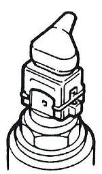
Please note that there ius a large earlier one (no longer available) and a later smaller one (used for many years). To use the later one and earlier owner will have to buy a new plenum to fit it.
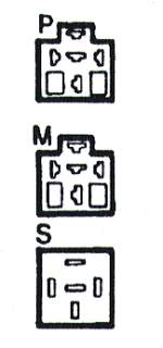
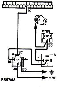
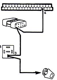
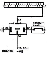
M=main relay
S="steering" (CONTROL) relay
This is presented in the normal checking sequence.
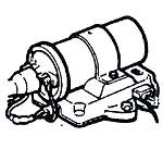
WHAT SOME ITEMS LOOK LIKE
|
|
|
|
Please note that there ius a large earlier one (no longer available) and a later smaller one (used for many years). To use the later one and earlier owner will have to buy a new plenum to fit it. |
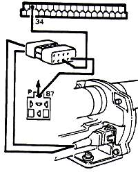
| Cold start enrichment | Connector to the ECU | P= pump relay
M=main relay S="steering" (CONTROL) relay |
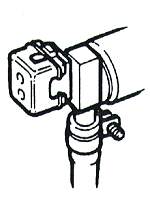
Air flow sensor - connector | Throttle Potentiameter |
|
|
|
|
|
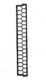
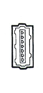
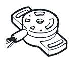
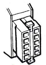
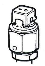
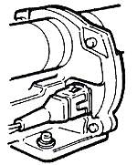
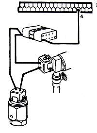
| Resistance Module box | Timed thermal contact | Air mixture valve | Coolant temperature sensor | Coil |
 |
Feeding of the ECU | Possible fault: |
| Connect multimeter (on volts) between Pin 10 and ground. Contact. | No reading: Check cables and connectors, check Main relay
by substitution of a new unit (this muts be a genuine Landrover 30amps,
0332 014 113)
Lower than 11 V: Check cables and connectors for a bad or corroded contact |
|
|
|
|
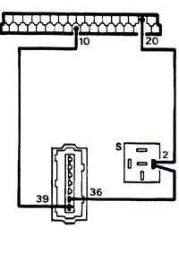 |
Fuel pump contacts | Possible fault: |
| Connect multimeter (on volts) between Pin 20 and ground.with Air flap closed | When closed: Something else than =V when flap closed: check
switch on air meter (flap) housing
When moving: No reading: Check wire harness from relay to air metre,
then from air metre to relais of fuel pump. Check the relay by substitution
of a new one. Check the pump by connecting a wire directly from battery
+ and - to the pump
|
|
|
|
|
 |
|
Possible fault: |
| Connect multimeter (on volts) between Pin 4 and ground. Turn the engine over with the starter. | No reading but starter turns: Check wiring harness from
ECU to relay and electronic regulator
No reading and starter does not turn: check starter and starter relay. Reading under 8V: check battery (connect another one) and starter |
|
|
|
|
 |
|
Possible fault: |
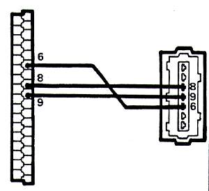
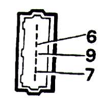
| Connect multimeter (ohms):
between Pin 6 and 8: 360 ohms between Pin 6 and 9: 560 ohms between Pin 8 and 9: 200 ohms |
Differing values: check cables with ohmmetre, check AFM flap to make sure it's completely closed. | |
|
|
|
 |
|
Possible fault: |
| Connect multimeter (Ohms) between Pin 13 and ground | Different values: Check cables and connector, change sensor
if readings still differ
Take only short readings as sensor may be damaged by heat from the multimeter's current |
|
|
|
+20°C = 2,1 to 2,9 kohms +80°C = 0,27 to 0,39 kohms |
 |
|
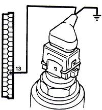
Possible fault: |
| from COIL
Make a connection between negative post of the coil and Pin 1. Connect multimeter (volts) between Pin 1 and ground Please notew that the siugnal from the negative post of the coil goes to the tachometre and then the ECU. Without it..the car will not start. |
No reading: check the connectors between coil and regulator | |
|
|
|
|
|
|||
 |
 |
 |
 |
| Possible fault: | |||
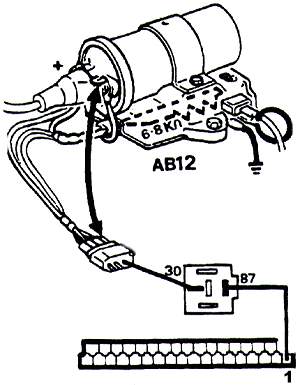
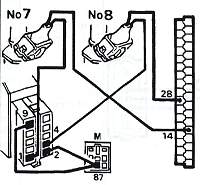
| Injector 7 | Connect multimeter (ohms) between Pin 14 & 87 of main relay | Reading below normal: Disconnect one injector
after another until you find the one with low or 0 resistance. Replace
it
If all are OK you must check the wiring harness and connectors as well as the resistance module |
|
| Injector 8 | Connect multimeter (ohms) between Pin 28 & 87 of main relay | ||
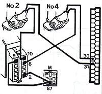
| Injector 2 | Connect multimeter (ohms) between Pin 31 & 87 of main relay | ||
| Injector 4 | Connect multimeter (ohms)e between Pin 30 & 87 of main relay | ||
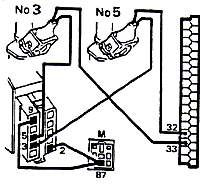
| Injector 3 | Connect multimeter (ohms) between Pin 33 & 87 of main relay | ||
| Injector 5 | Connect multimeter (ohms) between Pin 32 & 87 of main relay | ||
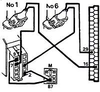
| Injector 1 | Connect multimeter (ohms between Pin 15 & 87 of main relay | ||
| Injector 6 | Connect multimeter (ohms) between Pin 29 & 87 of main relay | ||
|
|
|
||
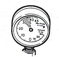
A fuel pressure gauge for testing |
|
Possible fault: |
| Mount the guage on the flexible line to the cold start enrichment injector. Turn ion the ignition and move the AFMr flap to close the electric circuit to the fuel pump | Pression 0: Check if fuel pump gets 12V, if
not so replace the pump relay and then the main relay.
If the pump gets 12 V check it's ground (a common fault) by laying a wire directly to the ground. If it still does nothing chances are good the pump is shot. Take it out and check it again on the bench. Pressure out of limits (above or below): Check for leaks on the complete circuit, coloring around line connections and leaking injectors, then fuel pressure regulator and anti-return valve-in this order. |
|
|
|
28-36 pounds with the engine off |
You can have the pumpo fiunction by having the ignition on and deflecting the flap in the AFM |
 |
(not onMorgan Flappers) |
Possible fault: |
| Connect multimeter (ohms) between Pin 34 and 87 of the fuel pump relais | No reading: Check wiring and connectors between fuel pump relay and air mix valve as well as electronic regulator. Than disconnect valve and check it by ohmmetre | |
|
|
|
 |
(on the plenum in back) |
Possible fault: |
| Disconnect thermotime switch. Successively ground the wires. Connect multimeter (ohms) between Pin 4 and ground | No reading: Check wiring and connectors between ECU, cold
start injector and thermotime switch.
Cut off: Check wires, connectors and cold start injector |
|
|
|
|
 |
|
Possible fault: |
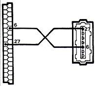
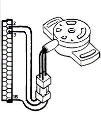
| Incorporated in the air flow sensor
Connect multimeter (ohms) between Pins 6 and 27 Take only short readings as sensor may be damaged by heat from curent from multimeter |
Reading unlimited: disconnect flow meter, connect Pins 6 and 27. If reading is now 0 the sensor is faulty. If reading still unlimited check wiring and connectors as well as ECU connector | |
|
|
+20°C: 2,28 to 2,72 kohms +50°C: 0,76 to 0,91 kohms |
 |
aka Throttle Potentiameter |
Possible fault: |
| Set multimetre on ohms, reconnect ECU, contact | ||
| Measure volts between green (-) and yellow (+) by the back side of the connector block near the ECU | 4,3 (+- 0,2V)
Lower or 0: check wiring and connectors |
|
| Measure ohms between green (-) and red (+) by the back side of the connector block near the ECU | 0.325 (+0.35)
Loosen screws and rotate (fiddle) sensor until reading is correct |
|
| The reading must increase steadlily progressively as you open the air flap | Progressive from 0,3 to 4,5V
If the reading jumps or fluctuates you must change the sensor. |
 |
|
Possible fault: |
| Disconnect the - wire from coil to relay. Contact off. Connect multimeter (ohms) between Pins 1 and 30 of the relais | Unlimited is correct. Anything else: Check wires and connectors, then replace relais by a new one. | |
| Contact | The resistance must drop to 0. Anything else: Check wires and connectors, maybe even the vacuum switch. | |
| Repeat the measurement at least once. |
 |
|
Possible fault: |
| Reconnect ECU. Contact. Pull back the rubber sleeve on the connector. Connect multimeter between Pin 6 (+) and Pin 9 (-) | 1,55V (+- 9,1V) This figures from the genuine book but I strongly suspect a fault here. I think it should read +-0,1V | |
| Connect multimeter between Pin 9(-) and Pin 7(+) | 3,7V +-0,1V | |
| Open the flap slowly: The tension must drop | 1,6V +-0,2V | |
| Abnormal results: Change the sensor |
 |
|
Possible fault: |
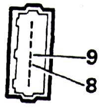
| Disconnect ECU. Contact. Pull back the rubber sleeve on the connector. Connect multimeter between Pin 8 (+) and Pin 9 (-) | Abnormal reading: Change AFM, (if you can find one) | |
|
|
|