Here is the installation instructions of one of the options, the Mulberry/Jones bracket.
Rear Mounted Battery Installation
Colin Jones & Peter Mulberry
A constant criticism of the later model cars starting system is the ability of the battery to retain charge, its overall capacity and perhaps more importantly that it seems to give little or no warning of failure. The availability of a quick replacement must also be considered especially if travelling away from regular Morgan repair and service locations.
Recently the Factory has realised this situation and has started fitting batteries in the ‘traditional’ location, to the rear of the seats. Because of the offset of the rear axle and considering which side of the car the starter motor is located the example shown (2002 +8) has the battery mounted behind the drivers (UK O/S) of the car. The kit could equally be fitted on either side depending on the owners preference however if the vehicle is a +8 and Anti-Tramp bars are fitted then it must be fitted to the O/S (behind the drivers seat in the UK).
As always all safety precautions should be observed, especially when handling batteries, safe and secure isolation of electrical terminals and systems are a straightforward operation provided sensible precautions are followed.
The complete kit comprises of ; -
Battery carrier / tray.
External mounting brackets (2)
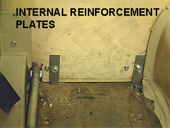
Internal reinforcement plates (2)
Battery cables with terminals already fitted. (1 long feed cable and one earth strap).
Battery cable junction box.
All nuts bolts and washers, cable ties and clips.
All you have to supply is a readily available battery of your choice, it is strongly advised to take the carrier with you to a local supplier and source a battery of the correct size and type. (Lorne or use https://www.gomog.com/allmorgan/CarBatterySizes&BatteryCutoffSwitches.html#NUMBERS)
Step 1.
Remove the right side seat, (drivers seat on a RHD or a pasenger's seat of a LHD), that side's front and rear carpets, rear parcel shelf carpet and the parcel shelf itself.
Step 2.
Raise the car to a convenient working height using axle stands and observing all safety precautions.
Step 3.
From the underside, offer up the empty battery carrier (Photo 1. Shows battery carrier) and mark the location of the external mounting brackets (Photo 2. Shows external mounting brackets).
![]() TIP!
Fit the brackets to the carrier loosely, and place the outermost bracket
adjacent to the crossmember vertical flange that is used to locate the
wooden ‘heelboard’. An assistant to hold the carrier from above greatly
eases this task.
TIP!
Fit the brackets to the carrier loosely, and place the outermost bracket
adjacent to the crossmember vertical flange that is used to locate the
wooden ‘heelboard’. An assistant to hold the carrier from above greatly
eases this task.
Drill through the plywood heelboard and fit the carrier with the bolts finger tight only, remember to fit the internal reinforcement plates. (Photo 3. Shows internal reinforcement plates).
Step 4.
From above, drill through the suspension roll hoop and locate the upper fixing again finger tight only.
![]()
TIP! If a jack is used under the carrier it
can be held in place and parallel to the
vehicles floor whilst the upper fixing location is determined
and drilled.
Step 5.
Take down the carrier, fit the battery securely using the cross strap, and mount the battery in the vehicle this time tightening all fixings and brackets as you install them. (Photo 4. Shows battery and carrier in situ).
Step 6.
Mark and drill a sufficient hole in the rear upper heelboard to allow the passage of the main battery cable and smaller lug, because the heelboard is constructed of wood there is obviously no need to insulate this hole. Run the cable along side the central transmission tunnel, under the lower edge of the gearbox cover and bring it vertically up the bulkhead ensuring it is cable tied away from the clutch pedal. It now passes in a smooth arc above the steering column and passes through the bulkhead main electrical grommet above the accelerator pedal (UK Markets). (Photo 5. Shows battery cable run through the car.)
![]()
TIP! Prior to feeding the cable through the grommet lubricate
it and the grommet, petroleum jelly works fine.
Step 7.
Set the terminal well away from the vehicles electrical system, it is sufficient to wrap the end in a clean cloth.
Step 8.
Now you have a choice, if you are not concerned about loosing your radio code or short term memory in the fuel injection electronic control unit (not a major issue as it will reset itself after approx. 50 miles) simply remove the original battery. If however you do not wish to loose your settings it is possible to connect the battery conditioner (if used) but the terminals of the battery have to be isolated at all times. Again wrap them in clean cloth and tape them to give a temporary isolation until they are needed.
The original battery lugs are now cut from the original leads and replaced with the supplied loop end connectors, it is important to ensure a good connection at this point and you are strongly advised to solder these in place. You will require either a VERY heavy duty electrical soldering iron or very careful use of a blow lamp (A plumbers type or micro blow lamp are perfect)
Step 9.
For ease of future maintenance and serviceability it is recommended to fit the junction box as supplied, this gives a convenient charging point and provides a jump start location should it ever be needed in the future.
To do this connect the original battery cable to one terminal of the junction box along with all the other (brown) leads as per the initial factory installation.
The ‘new’ cable goes to the other junction box terminal and the whole assembly is mounted at the rear of the original battery carrier plate.
The original earth lead is secured at the front of the original battery carrier plate. (Photo 6. Shows bulkhead connections and junction box).
Step 10.
At the rear of the car drill an additional hole through the rear suspension hoop, clean the surrounding paint to bare metal and fit the earth strap loop end.
Step 11.
Now check all cable runs, terminals and fittings to ensure they are not loose and or shorted to the vehicle ground. If all is in order fit the battery positive terminal to the rear battery, then fit the negative (earth) terminal. Remove the battery conditioner (if fitted).
Step 12.
Start the car and check again all cable runs and fittings.
If all is in order refit the trim, carpets and drivers seat, lower vehicle
to the ground.
Photos of the installation. (Colin's car)
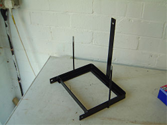 BATTERY
TRAY
BATTERY
TRAY
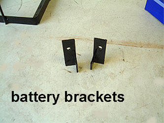 EXTERNAL CARRIER MOUNTING BRACKETS
 IN
CABIN REINFORCEMENT PLATES
IN
CABIN REINFORCEMENT PLATES
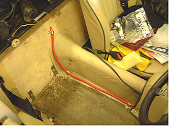 BATTERY CABLE RUNNING THROUGH CAR (NOTE CLIPS)
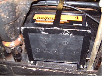 BATTERY
IN PLACE VIEWED FROM UNDERNEATH THE CAR
BATTERY
IN PLACE VIEWED FROM UNDERNEATH THE CAR
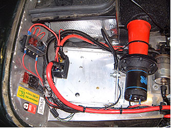
BULKHEAD MOUNTING OF JUNCTION BOX. (IGNORE EXTRA
FUSE BOX, ADDTIONAL WIRING AND HORN AS NONE OF
THESE ARE STANDARD. AS YOU SEE THIS GIVES THE
ADVANTAGE OF A SUPER JUMPSTART OR CHARGING LOCATION