 HOTWIRE
PLUG PINS AND WHAT THEY ARE FOR
HOTWIRE
PLUG PINS AND WHAT THEY ARE FOR
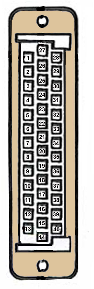
Bottom Row" - pins 1 to 13 (they're numbered from left to right
as shown on the plug)
1 Red/Green Idle bypass valve - circuit 1
2 Brown/Orange Power feed to the fuel injection main
relay
3 Yellow Throttle position sensor output/reference -
see also 20 and 25
4 Black Oxygen sensors (ground) and to the relay that
powers their heater coils
5 Grey/Black Tune resistor (through VIN LA451517 only)
6 Yellow Road speed input
7 Green/Blue Coolant temperature sensor (input) - see
also 25
8 Purple/Yellow Windshield defroster input, (IF FITTED)
9 White/Light Green Diagnostic connector output
10 Black/Yellow "Check Engine" lamp
11 Yellow/White Right bank of injectors - cylinders
2, 4, 6 and 8
12 Blue/Red Main relay "request"
13 Yellow/Blue Left bank of injectors - cylinders 1,
3, 5 and 7
Middle Row" - pins 14 to 27 (they're numbered from right
to left as shown on the plug)
14 Black Ground
15 Brown "Battery" supply
16 Blue/Purple Fuel pump relay "request"
17 Grey/Yellow Purge control valve output
18 White/Pink Diagnostic connector output
19 White/Grey "Ignition" supply
20 Red Throttle position sensor (input) - see also 3
and 25
21 Yellow/Black Air conditioning thermostat input (IF
FITTED)
22 Blue/Red Air flow sensor (input) - see also 25
23 Blue Signal from the LH oxygen sensor
24 Blue Signal from the RH oxygen sensor
25 Red/Black Ground side of coolant, fuel, airflow &
throttle-position sensors
26 Green/White Idle bypass valve - circuit 1
27 Black/Grey Ground
Top Row" - pins 28 to 40 (they're numbered from left to
right as shown on the plug)
28 Blue/Grey Idle bypass valve - circuit 2
29 Orange Idle bypass valve - circuit 2
30 Black Fault display data
31 Black/Green Diagnostic connector "request" input
32 Grey/White Fuel temperature sensor (input) - see
also 25
33 Black/Grey Air conditioning compressor clutch relay,(IF
FITTED)
34 Orange/Black Transmission gear switch signal (IF
FITTED)
35 Blue/Green Air flow sensor (input) - see also 25
36 Black/Green Air conditioning condenser fan output,
(IF FITTED)
37 (Not Used)
38 Brown/Black Fault display data
39 White/Black Engine speed signal cable (harness includes
6.8k ohm resistor)
40 Black Ground
Note:
1. Where two colors are given, the first is the
basic color and the second is a "stripe" or "tracer" color.
2. Pins 4, 23, 24, 30, and 31 were NOT USED on
vehicles that weren't equipped with catalytic converters.