#Pilot
REASONS FOR MORGAN CLASSIC DRIVETRAIN VIBRATION
This list of issues is not comprehensive.
I will keep adding to it as issues or contributions allow. However, it is a good start on the process that will end
your Morgan drivetrain vibration. Go to the diagnosis and checklist
section first. If the issue is in the front end..check out the FRONT END SECTION 12. And there is more remedial material within the Manual on each item mentioned here.
1. Motor
Accesories – Disconnect the belts of all motor accessories and run
motor. Many vibrations come from fans,
water pumps, etc. out of balance.
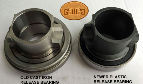 2. Clutch Throwout
or Release Bearing - When you install the (new) throwout bearing, remember that the
fork AND the springs go INSIDE THE GROOVE in the bearing - I see them installed
wrong all the time, with the curled ends of the spring capturing the flange on
the back end of the bearing - result is inability to get correct clutch
adjustment/free play.
2. Clutch Throwout
or Release Bearing - When you install the (new) throwout bearing, remember that the
fork AND the springs go INSIDE THE GROOVE in the bearing - I see them installed
wrong all the time, with the curled ends of the spring capturing the flange on
the back end of the bearing - result is inability to get correct clutch
adjustment/free play.
Install the flywheel (always have it resurfaced before this procedure), clutch
disc, pressure plate and clutch housing on the engine. Be advised that there
can be NO oil or grease on your hands, the flywheel or pressure plate friction
surfaces, or on the clutch disc. If there is, the clutch will grab (chatter)
when being engaged. Install the correct length clutch
fork on a 1½" long pivot that has the correct head type for the retainer
on the fork (refer to fork and pivot information previously discussed).
Position the fork so it sticks out of the clutch housing at about 4 or 5
degrees less than a right angle with the engine centerline (this would be when
looking down on the engine from above—the fork should be ahead of, or less than
a 90 degree angle by 4 or 5 degrees).
Install the transmission on the clutch
housing. The release bearing must be able to move away from the diaphragm
spring approximately 1/16 to 1/8" (this is the "free play"). At
this point you should be able to move the release bearing back and forward with
the fork. The bearing, when against the clutch, should leave the release fork
positioned at 4 or 5 degrees LESS than a right angle with the engine centerline
and allow it to be moved away from the clutch 1/16 to 1/8". If this
condition does not exists, do not install the assembly into the car until it
does. If not, you may need a different clutch release bearing or pivot or you
may have the wrong fork.
3. Motor
Mounts -
Morgan motor mounts are a wear part. The rubber interface dries,
cracks, deteriorates over time and must be replaced. Additionally,
bolts to other parts in the mount assembly, or to the frame or motor
will loosen and fall out.
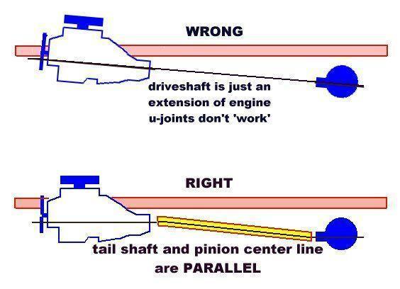
4. The Pinion
Angle
- This is tthe angle the pointy input shaft to the transmission makes
with its contact with the engine drive shaft. As a general rule, the
pinion angle shouldn't be set relative to the
ground, or exact level, but rather to the output shaft of the
transmission. The important thing is that the
two center lines are parallel.,
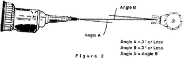
5. The Drive Shaft U-Joints
While it is possible to run at zero
degrees through the U-joints, something more than actual zero and less than
three degrees seems to run smoothest. Angle induced vibration will be
high frequency, twice engine RPM in direct drive. It may show up only on
acceleration or deceleration. Adjust the pinion down to correct acceleration
and up to correct deceleration vibrations, plus or minus one degree is usually
enough. Before adjusting anything, make sure the U-bolts holding the driveshaft
to the pinion yoke are not overtightened. Correct torque is 17 foot pounds and
no more.
6. Driveshaft (Prop Shaft) Phasing
Everything in
the drive train must operate in "phase" in order to minimize vibration,
noise and component wear. This sounds complex but it isn't as the
universal joints of the prop shaft take care of most of the task.
1.Check your U-joints for proper alignment. The rotational
speed of a universal joint varies or cycles as it turns through 360 degrees.
Since universal joints are almost always installed in pairs, they are normally
"phased" so this difference is eliminated. being canceled out by the two
joints. (As one joint speeds the rotation up, the other slows it down so
the rotational speed of the output is fairly constant.) Many propshaft
come apart for easy assembly, usually a splined shaft is used to transmit
power from one piece to the next. If the splined parts are connected without
insuring that the U-joints are in phase, a tremendous vibration can result
at speed.
 To check your U-joints, jack up your car and support it
on jack stands. (Never crawl under a car supported only by a jack.) A visual
check will tell you if your U-joints are lined
up correctly. Simply compare each end of the driveshaft to see if the yokes
on each end (the parts welded to the driveshaft tube itself) lie in the
same plane. (In a Morgan you may have to open the gear box cover access
panel). If they do not line up, or are at right angles to each other, it
is usually a simple matter to unbolt the propshaft and re-orient the splines
of the two pieces to bring the universal joints into proper phasing.
To check your U-joints, jack up your car and support it
on jack stands. (Never crawl under a car supported only by a jack.) A visual
check will tell you if your U-joints are lined
up correctly. Simply compare each end of the driveshaft to see if the yokes
on each end (the parts welded to the driveshaft tube itself) lie in the
same plane. (In a Morgan you may have to open the gear box cover access
panel). If they do not line up, or are at right angles to each other, it
is usually a simple matter to unbolt the propshaft and re-orient the splines
of the two pieces to bring the universal joints into proper phasing.
2. The major components at each end of the propshaft must be parallel to each other Think
about a complete automotive drivetrain from the side -this includes
engine, transmission, driveshaft and rear axle assembly. Part of the
"phasing" procedure includes making sure that the center lines of the
transmission and the rear axle input shaft are parallel. If the axis of
the pinion gear is parallel with the ground, then tail shaft of the
transmission must also be parallel to the ground. They can be
higher or lower than the other but they MUST be parallel to the ground.
And when these two components havedifferent centerlines to the any reference point (i.e. the ground) vibration must result!!! . Everything in the drive train must operate in "phase" in order to minimize vibration, noise and component wear.
Think about a
complete automotive drive train from the side -this includes engine,
transmission, driveshaft and rear axle assembly. Part of the "phasing"
procedure includes making sure that the center lines of the
transmission and the rear axle drive shaft are parallel. If the axis of
the pinion gear is parallel with the ground, then tail shaft of the
transmission must also be parallel to the ground. It can be higher or
lower but it MUST be parallel.
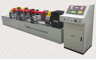
7. Driveshaft (Prop Shaft) Balance
If your shaft is not balanced with the actual
end yoke and U-joints, you have not fixed the potential vibration problems. A
driveshaft will not run  smooth and vibration-free unless it is straight and in
balance. The
smooth and vibration-free unless it is straight and in
balance. The 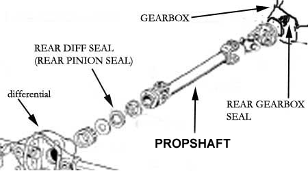 recommendation is to have shaft
dynamically high speed balanced at 10,000 rpm by a driveshaft professional. Typically, if the shaft is out of balance it will start to vibrate (and
make a droning sound) somewhere around 50-60 mph and then get worse as speed
increases to a point, and then get somewhat better at even higher speed...much like the vibration effect with a problematic Morgan front end.
recommendation is to have shaft
dynamically high speed balanced at 10,000 rpm by a driveshaft professional. Typically, if the shaft is out of balance it will start to vibrate (and
make a droning sound) somewhere around 50-60 mph and then get worse as speed
increases to a point, and then get somewhat better at even higher speed...much like the vibration effect with a problematic Morgan front end.
If making a new driveshaft correctly, measuring is done by putting the yoke in until it bottoms out and pull it back
3/4 of an inch. Measure the length of the U Joint centerlines and have a shaft
made with that length. If the yoke is too short to accomodate this correctly
you will have a stange vibration so check your drive shaft for proper
fit. Put the car on a drive on rack or on jack stands. With the car's weight on
the suspension as you would drive it, disconnect the shaft from the pinion
yoke. Push the drive shaft forward until it bottoms into the transmission. You
should be able to drop the rear u-joint cleanly past the pinion yoke without
resorting to a tool of any kind. Any clearance up to 3/8 inch is fine.
8. An Engine Anomally
Lean misfire or bad/fouled plug. A
very common cause of vibrations is a misfiring cylinder. A cracked spark plug insulator, smashed gap
or broken ground strap, are some of the causes. If you suspect a misfiring
cylinder, the best was to isolate it is to pull each spark plug wire one by
one, at idle, and note if/when there is a resulting rpm drop. Ten browse the GoMoG Manual for help.
9. Pilot (or Spigot) Bush
- Clutch pilot bearing or bushings: Pilot bearings or bushings began as bronze bushings placed at the end of the crankshaft
or in the center of the flywheel to support the
outboard end of the transmission input shaft. With Morgans, this
continued well into the 2000s. However, for most cars since the
1970s, pilot bearings are the ball bearing type
|
The
pilot
bushing is seldom thought of as a part of the clutch system but it is
one of
the most vital parts of the system. It holds and pilots the end of the
transmission input
gear into the crankshaft. It holds the input gear steady as its "nose"
twirls inside the bushing. If it is worn or not running "true", it
can
cause serious clutch problems or transmission failure. Pilot bushing
bore
runout should always be checked with a dial 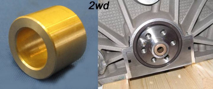 indicator and should be within .002
total. The bronze bushing type should be a press fit into the crankshaft bore. It
must be installed carefully. It should have between .001 and .003 clearance on
the transmission shaft when installed.
indicator and should be within .002
total. The bronze bushing type should be a press fit into the crankshaft bore. It
must be installed carefully. It should have between .001 and .003 clearance on
the transmission shaft when installed.
So the
job of the pilot bushing is to support the end of the input (main
drive) gear in the crankshaft. It only acts as a bushing when the
clutch is
depressed. This pilot bushing should be a light drive fit into the
crank bore.
Care should be taken when installing any pilot bushing as they are soft
and
easily damaged. A damaged pilot bushing can
bind on the input gear giving symptoms of clutch drag. Transmission
damage and early failure can be caused by a pilot bushing or crankshaft bore that
"runs out" in relation to the transmission locating bore in the
bellhousing. A slight scratch on the bushing will
cause a mild noise when the clutch is not enaged. This is annoying but
not harmful. Plus 8s are infamous for this.
It is advisable to check the bore
of the crank with a dial indicator before installing the pilot bushing (see
below). If the bore runs out more than .003 total, the crank should be set up
in a lathe and the bore trued up OR a special pilot bushing should be made that
runs out the same amount as the crank bore.
To check alignment, use a dial
indicator with the base mounted to the crank flange to check the transmission
pilot hole for concentricity to the crankshaft center line with +/- .010”. Check the face of the bellhousing (where the
transmission bolts up) for squareness to the back of the block. Variance should be no more than +/- .010”
side-to-side and top to bottom. Also check the
fit of the transmission to the bellhousing
and the fit of the pilot bushing to the
transmission input shaft.
| WATCHPOINT: There are sad rumors that these bushes are
very difficult to remove. Ignore them. Simply fill the hole with grease and use a
clutch alignment tool end or similar OD bolt, tap it into the hole and the grease
will force the bush out. When it works, you owe me a pint! |
9. Flywheel Runout
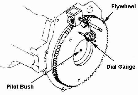
Check the face of the flywheel for runout
with a dial indicator. Runout should not exceed .005". If it does, the
flywheel should be resurfaced. If runout exists after resurfacing, the fault is
either in the resurfacing job or there are burrs, dirt, or dings on the
crankshaft or flywheel hub. Remember there is end play in the crankshaft
bearings and this must be held in one direction when checking flywheel runout
(or bellhousing face runout).
To check a
bellhousing, mount it on the engine it's going to be used with, make sure there
are no burrs or dirt on the block or bellhousing. All bellhousing to block
bolts should be in and tight. Mount the dial indicator on the crankshaft of the
engine using a suitable magnetic base attachment or mechanical clamping means.
The contact point of the indicator should be touching the bore of the
bellhousing. The indicator must be mounted rigidly enough so it does not move
on its mounting to prevent false readings. Rotate the engine by hand with the
spark plugs removed and observe the reading on the dial. The total number of
thousandths misalignment of the bore relative to the crankshaft is read
directly on the dial. Total runout should not exceed .007", with
.010" being maximum. The greater the misalignment, the sooner transmission
problems and failure will occur. A symptom of misalignment is unusual wear of
the pilot bushing. We have checked stock Chevy bellhousings on engines that
were out more than 1/32" (.032"). Some Ford one are reportedly worse.
Anything over .010" runout must be corrected before the engine and
bellhousing are put in service or you can count on pilot bushing, transmission,
and clutch problems, followed by transmission failure. The simplest way to
correct misalignment is to try another bellhousing or bellhousings. Machining
the bellhousing is the best cure but offset dowel pins are simpler. Shims
between the block and bellhousing will also work if you have the patience to
use this method. Offset dowel pins are sometimes available from "speed
shops."
Vehicle Drive Train Vibration Diagnosis Checklist
|
PART
|
POSSIBLE PROBLEM
|
| BODY |
|
|
|
Body
|
Loose
Body Mounts
|
|
|
Body
|
Rusted
Body Mounts/Brackets
|
|
|
BRAKES
|
|
|
|
Brakes
|
Calipers
|
Loose
Caliper Bolts
|
| CLUTCH |
|
|
|
Clutch
|
Pilot
Bushing
|
Loose,
Worn
|
|
Clutch
|
Flywheel
|
Out of
Balance
|
|
Clutch
|
Flywheel
|
Out of
Balance, Surfaced too much, Loose, No Dowel Pin
|
|
Clutch
|
Clutch
Pressure Plate
|
Plate Off
Center, Out of Balance, Bent Housing
|
|
Clutch
|
Clutch
Disk
|
Out of
Round, Dropped, Out of Balance
|
|
Clutch
|
Bellhousings
|
Cracked
or Hole not Concentric to Crankshaft
|
|
ENGINE
|
|
|
|
Engine
|
Water
Pump Shaft
|
Bent,Loose Bearing
|
|
Engine
|
Fan
Clutch
|
Loose,
Bad
|
|
Engine
|
Fan Blade
|
Bent, Out
of Balance
|
|
Engine
|
Balancer
|
Loose,
Spun on Rubber, Bad Keys
|
|
Engine
|
Motor
Mounts
|
Cracked
|
|
Engine
|
Tune-up
|
Misfiring
|
| Engine |
Engine timing off |
|
| Engine |
Carb |
Misfiring |
| Engine |
Crankshaft Rear Flange |
Bent loose flytwheel bolts, worn dowel pin |
| FRAME |
|
|
|
Frame
|
Cracked
Bent or Rusted Frame or Crossmembers
|
|
|
Frame
|
Cracked Front Frame Extensions
|
|
|
Frame
|
Loose Bumper Brackets,
Impact Bars
|
|
| REAR AXLE |
|
|
Rear Axle
|
Flanges
|
ent
Flange or Loose Bolts
|
|
Rear Axle
|
Flanges,
Half Shafts
|
Wrong
Combination, Wrong Alignment
|
|
Rear Axle
|
Half
Shafts
|
Bent, Out
of Balance, Loose UJoint Holes
|
|
Rear Axle
|
U-Joints
|
Not
Seated Properly, Off Center, Wrong Caps, Clips Missing
|
|
Rear Axle
|
Axle
Yokes
|
Bent, Not
Seated U-Joints, Not Machined Correctly, Loose Bolts
|
|
Rear Axle
|
Pinion
Flange
|
Bent,
Machined Wrong, Loose Bolts
|
|
Rear Axle
|
Pinion
Snubber Bushings
|
Loose or
Worn Out Cushions or Loose Bolt
|
|
Rear Axle
|
Pinion
Snubber Bracket
|
Slotted
Bracket Holes or Loose Bolts
|
| STEERING |
|
|
Steering
|
Wheel
Bearings
|
Loose or
Bad Bearings
|
|
Steering
|
Steering
Gearbox or Rack
|
Loose
Internally or Loose from Frame
|
|
Steering
|
Steering
Column
|
Loose,
Bent
|
| Steering |
Column Bush compromised |
Replace |
| Steering |
Column Adjuster untightened |
|
|
Steering
|
Tie Rod
Ends
|
Loose
|
| SUSPENSION |
|
|
|
Suspension
|
Front
Stub Axles
|
Bent
Spindles, Loose Bolts
|
|
Suspension
|
Anywhere |
Loose or Missing Bushings
|
|
Suspension
|
Ball
Joints
|
Loose,
Not Lubricated, Need Replacement
|
|
Suspension
|
Shocks
|
Worn, Loose, Fit too tight, Leaking, Bolt
or Grommets
Missing
|
| TRANSMISSION |
|
|
|
Transmission
|
Trans
Input Shaft
|
Bent
|
|
Transmission
|
Trans
Output Shaft
|
Bent
|
|
Transmission
|
Trans
Tailhousing Bushing
|
Worn
|
|
Transmission
|
Trans
Mounts
|
Cracked or rubber worn/missing
|
|
Transmission
|
Driveshaft
|
Bent, Out
of Balance, Balance off or Weight Missing
|
|
Wheels/Tires
|
Wheels
|
Bent,
Loose Lug Nuts, Wheel Adapters
|
|
Wheels/Tires
|
Tires
|
Bad, Out
of Round, Out of Balance, Broken Cords
|
| TESTING & DIAGNOSIS |
|
|
|
Test
Drive
|
Check at
what speed vibration comes in
|
|
|
Test
Drive
|
Check whether it is MPH of RPM related
|
|
|
Test
Drive
|
Check
whether it goes away with clutch disengaged
|
|
|
Test
Drive
|
Get up to speed where vibration is the greatest,
Then:
|
|
| DIAGNOSIS |
|
|
|
Diagnosis
|
Disengage Clutch, Does Vibration Go Away?
|
|
|
Diagnosis
|
With Clutch Disengaged, Rev Motor Up & Down
|
|
|
Diagnosis
|
Does the Vibration Relate to Engine or Road Speed
|
|
|
Diagnosis
|
With Car Sitting Still, Rev Up Engine to Check for
Vibration
|
|
|
Diagnosis
|
Short Out Cylinders one at a time
|
|
|
Diagnosis
|
Disconnect All Belts to Eliminate Front Engine
Accessories
|
|
|
Diagnosis
|
Install a Different Set of Wheels and Tires to
Eliminate Them as a cause
|
|
|
Diagnosis
|
Run the Vehicle on the Hoist with Jack Stands at Rear to
Load Suspension properly
|
|
|
Diagnosis
|
Spin
Balance Wheels on Vehicle
|
|
|
Diagnosis
|
Hoist Testing will Eliminate Front Suspension, Steering, and
Road Vibration
|
|
|
Diagnosis
|
Using a Stethoscope or
Wooden Dowel on Components will Amplify Noises and Vibrations
|
|
| NOTES |
|
Notes:
|
Clutch & Flywheel Problems Tend to Be Felt at
around 1800 and 3600 RPM
|
|
|
Notes:
|
Tire Balance Problems Tend to Get Worse With
Speed
|
|
|
Notes:
|
Front End Problems Can Come and Go With Different Speeds.
|
|
|
Notes:
|
Front End Problems Tend to be Felt in the Steering
Column
|
|
|
Notes:
|
Clutch, Flywheel, and Trans Problems Tend to be Felt
in the Shifter
|
|
|
Notes:
|
Rear End Problems Tend to be Felt in the Seat
Bottom
|
|
|
Notes:
|
Body, Frame and Bumper Problems Tend to be Felt in
Body Vibrations
|
|
|
Notes:
|
Vibrations Tend to Come
From Items With Great Mass at a Great Distance from Centerline
|
|
|
Example:
|
You Can Get a Vibration
from a Tire, But You Wouldn't Get One From a Spindle Nut
|
|