 1133 Chatmoss Dr., Va. Beach, Va. 23464; (757) 495-8229
Originally written: circa 1993
Last updated: June 7, 2009
When I bought my Morgan, my dad used to joke about needing a cabinet maker because of all the wood. When I describe the car to friends, they always kid about having it covered by a termite contract. I think the best joke about the car came from a co-worker, "buy a real car and save a tree!". This leads me to the topic I'd like to talk about in this article: restoring the wooden body subframe.
The factory did not seal the wood very well. When my car was totaled
22 years ago, I had to replace all the woodwork behind the doors except the
right side rear fender arch. I sealed all the new wood (left fender arch,
inner panel, etc.) with a wood primer/sealer but did not touch the right
side wheel arch and inner panel. The car left the factory in December
1965, making the two fender arches 3 years different in age. When I
removed the skin, I found that the treated wood was in great shape (no rot)
some 25+ years later. The untreated wood is a different story. The back 2
inches of the fender arch has rotted away and the inner panel must be
replaced. This time I wanted to seal the wood forever so I used the WEST
system epoxy.
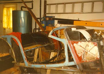
Removing the skin
After the body is off the car, it was placed on saw horses to allow
easy access for disassembly. The first undertaking was to remove
everything from the firewall.
The firewall was removed from the wood subframe by removing the
numerous wood screws around the perimeter of the firewall and the 2
hex head bolts that hold a steel stiffening bar to the firewall and wooden
frame. Now comes the hard part, removing the sheet metal skin from the
wood. The skin is held to the wood by a few screws and a LOT of nails.
Removing the nails turned out to be a real chore. I spent hours trying to
remove them with diagonal cutters (broke 2 pairs of them) and end cutters.
 Next I tried modifying a screwdriver by grinding the blade to a sharp
edge. I was hoping that I could drive the screwdriver under the sheet
metal and pop the nails up enough to grab them with the dikes. This worked
better than just the dikes, but not as well as I had hoped. The next
approach was to use a dremal tool to grind off the heads of the nails.
This didn't work at all. I kept cutting into the sheet metal. Regardless
of the method I used, I couldn't work at this for more than 15 to 20
minutes before I got so frustrated I wanted to take an ax to the whole
thing.
Next I tried modifying a screwdriver by grinding the blade to a sharp
edge. I was hoping that I could drive the screwdriver under the sheet
metal and pop the nails up enough to grab them with the dikes. This worked
better than just the dikes, but not as well as I had hoped. The next
approach was to use a dremal tool to grind off the heads of the nails.
This didn't work at all. I kept cutting into the sheet metal. Regardless
of the method I used, I couldn't work at this for more than 15 to 20
minutes before I got so frustrated I wanted to take an ax to the whole
thing.
The Secret
I found the secret by accident. I had taken my youngest son to the
hardware store a few days earlier. He decided that he wanted to get a
tool. He picked out a small claw hammer with a removable head and several
other tools in the handle. In desperation, I decided to try using his
little "toy" hammer. It worked like magic. I was able to drive the claw
of the hammer under the sheet metal on either side of a nail and pry up the
nail with a minimum of damage to the sheet metal. I had spent 2 hours
using the dikes and screwdriver to remove 2/3 of the nails holding
only 1 quarter panel to the rear fender well. After I started using the
claw hammer, I removed the remaining 1/3 of the nails on the one and all
the nails on the other quarter panel in less than 15 minutes.
After all the sheet metal is removed, it is time to start removing the screws which hold the wood subframe together. Removing some of these screws can be a real problem.
Here are a few hints to help a screwdriver get a better bite:
- the slots in the heads of the screws should be cleaned with a knife.
- ensure the blade of the screwdriver is flat and that the edges are not rounded - if so, regrind the blade.
- hitting the top of a screwdriver with a hammer while trying to turn the screwdriver helped on the stubborn ones.
- on screws that just won't move, I found a brace and a screwdriver bit
usually did the job.
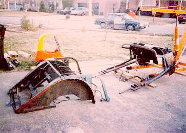
The wood subframe can be separated into two parts. There are 2 screws holding each of the rear arches to the door sill plates, and 2 screws holding the rear quarter panel frame to the sill plate. The figure shows the basic wood subframe and the size of the screws holding it together.
To separate the two fender arches, start by removing the wooden U
formed by the rear chassis mounts which are attached to the rear inner
fender panels and the rear cross brace. Be careful as this U is relatively
fragile. The fender arches are attached to the chassis mounts by three
screws (6b). It may be necessary to use a rubber tap hammer to remove the
fender panels from the groves in the chassis mounts. This U can now be
disassembled by removing the 2 screws that hold the cross brace to the
chassis mounts. The trunk rack and the spare tire rack can be removed
by unscrewing the nuts on the carriage bolts and removing them.
Finally, fixing something!
When rehabilitating the original wood pieces I removed the paint
with paint remover, and sanded each piece. The small nail and screw holes
were filled using toothpicks or matches dipped in the epoxy. Screw holes
that had rotted or otherwise been disfigured were repaired by drilling them
oversize, and inserting a piece of dowel rod which had been dipped in
epoxy. After filling these holes, the remaining epoxy was used to start
sealing the wood. When the epoxy dried, I sanded each part with 60 to 100
grit sandpaper and a second coat of epoxy was applied and sanded. Now the
wood was ready to be reassembled and painted. Instead of coating each
individual part, you could coat the entire wood frame with the epoxy;
however, I chose not to do so. I wanted the option to disassemble the
wood, if necessary, without having to cut it apart.
I had to make several new wood parts: trunk back, trunk deck, the door sill plates, right rear fender well panel, door panels, and the gas tank bed, floor boards. Most of the replacement parts were initially cut by using either a band saw or saber saw. Final shaping was accomplished by clamping a template (either the original part or a poster board pattern) to the part and sanding the new part with a 1" belt/disc sander until it matched the template.
To make the new front floor boards, I purchased some poster board to make patterns. I measured the chassis and sketched it on the poster board and cut them out. Once the patterns fit, they were traced onto a piece of 1/2 inch of CDX plywood and cut out using a saber saw. I made one minor change from the original floor boards. The factory cut them so they laid next to the little fore/aft stringers that the transmission bracket mounts to. Instead, I increased the width of the floor boards so they laid on the stringers. Since the stringers are not flush with the bottom angle of the chassis, the floor boards were notched to accommodate the height of the stringers. (The notch was made by making several cuts on a table saw with the blade set to the height of the stringer.) Since the new floor boards go completely across the angle iron stringers, the floor boards must be notched to fit around the transmission mount bracket and the emergency brake hardware.
The seatpan part of the floor boards was also modified. Originally it
consisted of 2 pieces with a cutout in them, apparently to allow access to
the grease fittings on the rear U joint. Since the new U joints I
purchased did not have grease fittings, I decided to make the seatpan one
piece.
My first mistake
The original gas tank bed was 3/4 inch thick. I hadn't checked the
clearance between the rear springs and the bed, but figured that if I
epoxied 2 pieces of the 1/2 inch plywood together, it would not hurt.
Well, after I had the gas tank bed re-installed in the chassis and the gas
tank mounted on it, I tried to install the rear springs. They were laying
directly on the gas tank bed. I had to take everything apart and notch
both sides of the bed so they were 3/4 inch thick to allow the springs to
fit.
Making new pieces
The sill plates were surprisingly easy to make but require access
to several expensive machines. When the car was totaled, I had purchased
a new sill plate but didn't use it. Consequently, I had a good template to
work from. Since both sides are mirror images of each other, the one
template could be used to layout the two new pieces. I purchased a piece
of 1 inch thick oak and ran it through a planner to get it down to required
3/4 of an inch thick. Next I set the template on the board and traced 2
sill plates. I used a band saw to cut the sill plates to the approximate
size. Then I clamped the original sill plate to one of the rough blanks
and used a 1" belt/disk sander to sand off the excess wood. The little
curve, near the back of the sill plate, was smoothed with a drum sander
chucked up in a drillpress. The hard cut was the curve, in the side of the
sill plate, where the fender fits. To make this, I clamped the original
sill plate to the new one, then marked off several lines across the
thickness of the boards. Next using a pair of dividers, I measured the
thickness of the original at each of the lines and transferred this to the
new piece. The curve was sketched by connecting all the marks. The cut
was made using a vertical milling machine. (It could have been made
using a table saw, but it would have been harder, as a spacer would have to
be made.) The same process was used to make the 2nd sill plate. Once the
new pieces were finished, they were coated with epoxy, sanded, recoated
with epoxy, and resanded.
The right fender arch had lost the back 2 inches or so due to wood
rot. The front lip, where it bolts to the sill plate, also had rotted, and
the inner panel had to be replaced. The new inner panel was made by
tracing the outline of the old panel on a piece of 1/2" BCX plywood and
cutout using a saber saw. (The original panel was 3/8 inch plywood. I had
intended keeping it stock. Somehow I just blew it. However, after getting
the new panel made, I decided that the extra 1/8 inch would not make that
much difference - I hope!) The final shaping was done using the belt/disk
sander. Using the transfer punch set, I marked and drilled all the holes.
Next, 2 coats of epoxy were applied and sanded. To repair the arch, I
started in the back about 2 inches forward of the rot and drew a diagonal
line (about 4 inches long) across the arch. (This would give more surface
area for the patch to mate to.) The rotted section was cut off using a
band saw. I bolted the side panel back on so the angle between the panel
and the fender arch could be measured using a protractor on a ruler
(similar to a combination square). Once the angle was drawn on a 3/4"
piece of oak, it was set on the fender arch and arch lines were extended
using a yardstick. The patch piece was cut using a band saw. Next, the
fit was checked by setting it in place. The final shaping was done
using the belt/disc sander. When a good fit was achieved, the patch was
clamped to the arch and 2 holes drilled so the patch could be screwed to
the arch. Everything was disassembled again and epoxy was applied to both
the patch and the arch, and the patch was re-screwed to the arch. The
entire arch was coated with 2 coats of epoxy. The front lip was rebuilt
using epoxy and a filler to thicken it. I placed masking tape around what
was left of the lip, to form a dam, and applied the thickened epoxy to the
damaged area.
What holds the door skins on?
I finally decided to tackle the doors. After I removed the
interior panels, I couldn't figure how to remove the door skin from the
wooden frame. I finally decided to call John Sheally again and ask how the
doors were built. He said "the wood door frame is assembled and a metal
flange is nailed to it. Then the door skin is set on and the edges of the
skin are crimped over the metal flange." He suggested not trying to
disassemble the doors. I will have to sand the wood and the inside of the
door. (I don't suggest using any paint stripper, and if it gets under
the wood it would be difficult to neutralize.) After cleaning the inside
of the door and the wood, I will apply epoxy to the wood and repaint the
metal. The factory makes the door inner panels using 1/8" plywood which
has disintegrated. I made the replacement panels from 1/4" plywood sealed
with epoxy and will cover it with 1/4" foam rubber and naugahide.
The firewall attaches to the front of the wood subframe. This wood is composed of 3 separate pieces with a small piece of plywood inserted between each vertical piece and the horizontal piece. I cleaned up the slots with a milling machine. However, they could have been cleaned with a table saw. To make the braces, I inserted a piece of poster board into each slot and traced the outside of the wood. I cut out the template and traced it on to some scrap 1/4 inch plywood and cut them out using band saw. The final shaping was done using the 1" belt/disc sander.
The last piece, to be made were the 2 curved pieces that support the
sheet metal rear deck and fit on the outer edge of the fender arch just
behind the cross brace. To get the curve, I used a curve tracing tool
(made up of a lot of little rods held together by a cross brace). I
placed this on the fender arch and tapped the top to get a nice fit. This
curve was then traced on a small block of wood. The height of the cross
brace was measured and transferred to the block of wood and the upper curve
was sketched freehand. I used a band saw to cut the part out. Final
shaping and smoothing was done using a drum sander chucked up in a
drill press.
Closing
Well, that should be enough for this time. Next time I'll discuss
installing the front suspension subframe, rear springs, differential and
reassembling the chassis.
Enjoy your Morgan
John
List of Fasteners used in the wood subframe
Listing of Wood Screw Pilot Hole Sizes
Decmial to Fraction conversion chart
Return to the Index of Tech. articles
To email me with comments or questions.