Restoring an automobile is hard work. Overlooked somewhere between the initial optimism of a just-discovered project car and the near perfect finished car are untold hours of misery. You can’t fathom the long hours and seemingly endless cost: your mind won’t let you. Its like watching a shoot-em-up on the boob tube: you see it happening, but you don’t feel the pain.
It stands to reason, then, that anything capable of helping to ease the suffering would be as welcome as an indentured assistant. This is especially true when performing frame-off restorations. While separating the body and frame is the only means available to truly restore used and abused sheet-metal and steel, it can instigate a whole new set of problems: just where, for example, do you put the body… and how can you turn it over without crushing the roof?
Walk into a professional auto restoration shop, and you’ll find the answer. Facilities tailored to such labor-intensive tasks usually sport an array of extremely specialized equipment designed to lessen not only the grief associated with such an undertaking but the time spent performing such chores. One such component is a body rotator., a mass of steel tubing designed to allow virtually unobstructed access to vintage sheet-metal. Its exactly the piece of machinery the home hobbyist could put to good use, but is usually prohibitively expensive for anyone not in the business of making it pay for itself. Suppose, however, that we told you how you could build a respectable rotator yourself for about $200 in materials? All of a sudden, ownership of a body rotator jumps from the options list to required equipment!
Building a body rotator is a fairly easy assignment for anyone with hands-on experience with shop tools and a welder. This isn’t high technology: what you’re creating is, quite simply, a rather crude tool capable of sup-porting the weight of a car body without folding, spindling r mutilating the sheetmetal. As we learned while watching as the gang at Jeff Lilly Restorations crafted such a homemade body jig, the actual construction of the rotator is a straightforward (albeit involved) affair: all you need to guard against is using tubing of insuffi-cient strength and ensuring that all necessary welds are satisfactory. In fact, Jeff went so far as to list all the requisite tubing for fabricating a rotator, outlining the steps necessary to assemble it, to boot! A bare-bones schematic of the finished product might come in handy: you may find it useful to make a sketch of all the parts and how they’re supposed to fit together before initiating construction.
As when crafting or creating anything of a mechanical nature, Lilly points out that the usual safety precau-tions need to be taken when operating shop machinery or welding equipment: the utmost care must also be taken when attempting to install or remove a body on this tubular steel rack. There are. In addition, certain as-pects of construction that demand a second set of hands (that indentured assistant will come in handy here). Properly assembled, however, this inexpensive rotator should meet the demands of most hobbyists, and ac-commodate the dimensions of most makes and models.
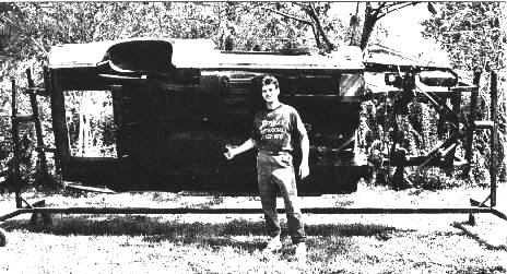
Granted, it may mot fit in your garage, but it makes a great conversation piece for the backyard. Seriously, the cost and simplicity of this rotator makes it a near necessity for earnest home restorationists. Besides, if you’re like most enthusiast, you probably know a few like-minded power brokers who have shied away from restoring vintage iron due to lack of such specialized tools. You could easily make up the cost of the rotator by just loaning it out a time or two! Even if it never leaves your home, the time you will save on your project, will be many times over what it will take to build this unit!
SQUARE STOCK
#1: The main standing supports: two (2) five-foot lengths of 2.0-inch tubing;
#2: The arms that rotate: two (2) four-foot of 2.0-inch tubing;
#3: Wheelbase bottom extensions (for connecting the rotators): two (2) one-foot lengths of 2.0-inch tubing;
#4: Attaching arms (to create L-shaped adjusting sliders for in/out and up/down movement); these bolt to body
or frame: eight (8) 11-inch lengths of 2.0-inch tubing;
#5: Center outside connectors for attaching both ends of rotator: two (2) six-foot lengths of 2.5-inch tubing;
#6: Wheelbases (on which tires will be attached): two (2) four-foot lengths of 2.5-inch tubing;
#7: In-and-out adjusters: four (4) six-inch lengths of 2.5-inch tubing;
#8: short in-and-out adjusters: four (4) three-inch lengths of 2.5-inch tubing;
#9: Height-adjustment sliders (to later be welded with large round tubing): two (2) one-foot lengths of 2.5-inch
tubing;
#10: Main center connector: one (1) seven-foot length of 2.0-inch tubing;
In addition, you will need several lengths of round stock. This should be purchased as used stock since in new condition it is sold only in 20-foot-long lengths, and you will only require two-foot-long sections of each size. You will also need two feet of 5/8-inch threaded stock (with nuts) to be used to keep assembled rotating stock together.
ROUND STOCK
#11: Large round stock: two (2) eight-inch lengths of 3.5-inch diameter (3/16-inch wall thickness) tubing;
#12: Small round stock: two (2) eight-inch lengths of 3.0-inch outside diameter tubing;
#13: Threaded rod: two (2) 11-inch lengths of 5/8-inch rod.
PIERCED PARTS
Most (although not all) of the cut and numbered tubular steel sections will require a collection of holes drilled into them. Again, we’ve distinguished each different length and size by number. It’s critical to the success of your rotator that any drilled hole is measured the correct distance and centered on the side of the steel stick. It’s easier to mark all the parts for each length, then drill the requisite holes. Unless otherwise specified, use a 29/64-inch bit in a drill press; drill all members of each specified length them same.
#1: Measure from one end and drill a hole every six inches, or every three
inches for greater adjustment;
#2: Measure from one end and drill a hole every two inches; a total of five holes
are needed; then, locate the exact center and drill a 1-5/8-inch hole (for
attaching the unit to the large round stock during assembly);
#3: No holes necessary;
#4: Two pairs of holes required. First, measure from one end and drill four
holes, two inches apart. Next, repeat the first hole (two inches from the end)
on the remaining three sides (this will be used as mounting holes to the
frame and body);
#5: Measure two inches from each end, and drill one hole at each end. Weld
a 7/16-inch nut at each end for tightening the bolt down to hold into place;
#6: No holes necessary;
#7: Measure 1-1/2-inches from one end, and drill one hole;
#8: Measure 1-1/2-inches from one end, and drill one hole;
#9: Measure and drill for one 5/8-inch hole, two inches from one end;
#10: No holes necessary;
#11: Measure and drill one hole two inches from one end; weld a 7/16-inch
nut onto the hole (to be used as holding device
When starting, remember to first prepare the parts: new steel has a light film of oil on it to keep if from rusting. Use lacquer thinner or prep-sol and wipe it clean. For simplicity's sake, all references to specific lengths and sizes of the cut stock are by number (see "Steel Me Away" sidebar)
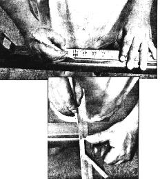
Let's get familiar with the techniques of proper measuring, tools and leveling of steel before cutting. Take a tape measure and a carbide tip scribe (the scribe will leave a good visible mark) and mark on the steel the correct lengths to be given. (A good method is to make a "V" mark, with the point of the "V" should be on the exact length needed to assure that you are in the direct center of the measurement) Now take a hand-held square (straight edge) and hold it on the point of the "V" and scribe your straight lines.
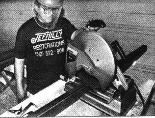
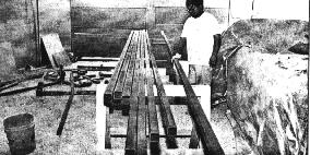
In order to cut through the steel, Jeff recommends enlisting the help of a shop equipped with a chop saw along the lines of a model 2730 Black and Decker Industrial chop saw. "Because of it's high-horse-power motor, it's the best of many others I've used and it will cut through big stock easily without bogging, " Jeff pointed out. You will need two 14-inch cut-off blades to do the job.
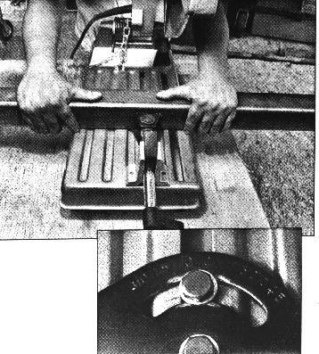
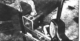
The steel needs to lay level on the chop saw. Level it by placing blocks on one end if need be, or have someone help to hold it up so that every point of the metal is making contact. Then wind the crank and tighten firmly. This is a close up of the angles that can be cut on the chop saw. For this rotator, we're only cutting straight (note how the lines at the "00" marks line up). This will assure that you're cutting straight with the saw.
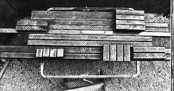
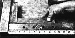
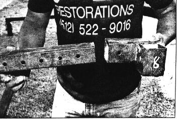
Here, you can see what length #1 (two five-foot lengths of 2.0-inch square tubing) look like after being drilled with holes every six inches. Once all holes have been drilled into the assorted pieces of steel stock, take a grinder and make sure all holes are smooth and free of burrs (the same goes for the ends of the steel stock).
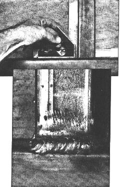
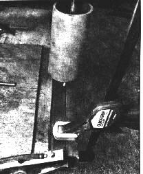
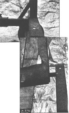
Put the main post (#1) flush against the base bottom (#6) and weld it in place. (You may want to use something to prop up the smaller post to keep it flush with the larger base tube.) Lilly recommends using a Mig welder, preferably with at least 100 amps, a 0.30 wire and infinite heat control for deep penetration. See how the weld does not overlap the top: this is important because we'll be welding the connector at this point, and in order for it to rest flat you must not overlap the top edge with weld.
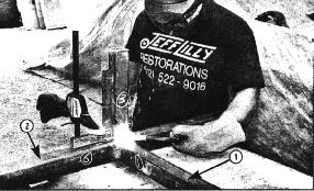
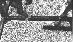
Note in this photo how the main slider for height adjustments (#1) has all holes running parallel (arrow 1). To this we've added first the base (#6, arrow2) for the tires; next, the extension connector (#3) is welded to the base. Use a pair of locking pliers to hold it in place, and a square to ensure level. Tack weld it on each side, check for accuracy, then weld it solid.
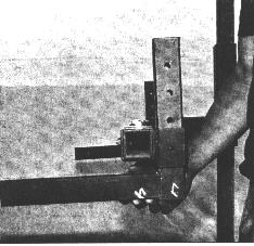
Pictured are two lengths of #4 tubing. Note that this section of stock requires two sets of holes (see "Piercing Parts" sidebar); the side with a hole on one end is the piece that will bolt up to the frame or body. The side with four holes in it will slide up and down as the adjustment piece against the main arm of the rotator. After you get the L-shaped pieces squared up, weld where the two pieces meet. As you first tack weld, make sure to check that the square still fits precisely in the comer and there are no gaps.
Take one length of #8 stock and one length of #7 (see how the numbering system comes in handy?). They should overlap on one end and be flush on the other (see arrow). These pieces combined will give the #4s you just welded the adjustment and bolt-holding ability when connected to the #2 arms you'll be working on.
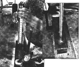
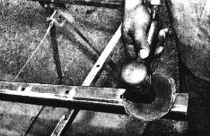
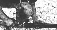
Take your slider (one length of #9 tubing) along with one length of 5/8-inch threaded rod #13). As specified in the drilling sidebar, center and drill a 5/8-inch hole two inches from one end so you can insert the rod into place. Place the rod 1/8-inch into the hole. Be careful not to go past the inside wall or you won't be able to slide this tubing for adjustment. Weld the rod straight-up flush in the hole.
Next, place one length of large round tubing (#11) over the rod and center if. Then weld it 360 deg. around solid.
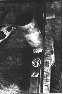
Likewise, take one length of small round tubing (#12), place if dead center on the rotator arms (#2), and weld it solid 360 deg.
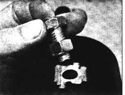
Weld a 5/16 nut with bolt threaded through it for centering on the large round tubing (#11) where the hole was drilled, and also on the square tubing center outside connectors (#5), where holes were drilled previously for keeping center of rotator together once adjusted for your body or frame.
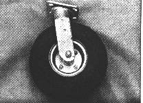
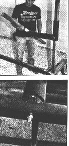
Here are the tires Lilly used (from Northern Hydraulic; 800/556-7885--about $25 each) or online - www.northern-online.com. You'll need two I0-inch swivels for the front (PN 11000) and two l0-nch rigids for the rear (PN 11074). Weld or bolt them to the stock designated as wheelbases (#6). These will support 500 pounds each, giving you a total of 2000 pounds capacity. Remember, this rotator was built for semi-stripped-down bodies, not 8000-pound school buses.
If it will make you more at ease, go ahead and weld an additional support bracket to the bottom out of 1xl-inch square tube (arrow). Now paint or epoxy the entire rotator with Ditzler DP 90 to avoid rust. Yet another option you can try if you want more room for sand-blasting and/or painting: cut four (4) two-inch long sections of one-inch O.D. round tubing and use them where rotator bolts up to body or frame. Again, this isn't a strict necessity.
Once the basic framework is finished, you'll need to forge ahead and piece together the mechanism for actually rotating the body. Depending on your particular application, during assembly use 3/8 x 9inch-long bolts (with nuts) and by and position the center round rotating stock at a height that would be in the center of your body or frame. This will aide in the easiest rotating. Slide the adjustment slider (#9) onto the main standing support (#1).
Next, take the six-foot-long side extension connector (#5) and slide it onto the end of the rotator at the wheelbase bottom connector (#3). Again, take note of the numbers seen on the parts.

Attach the main center connector (#10) to the outside connectors (#5).
Remember the earlier assembly using the short lengths of round tubing and the threaded stock? Slide the arms with the small round stock into the main large stock assembly, and place a nut on the end of the threaded stock that came all the way through (#9); this will keep it together.
Slide the L-shaped bracket into place and make sure they're pointing in toward the center of the rotator. Attach a bolt to hold and proceed.
Place the adjustment sliders you created (#7 and #8) onto the arms (#2).
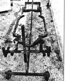
Finally, assemble to frame or body. There are so many body and frame styles that it's impossible to list. Use your ingenuity to hook it up. Hook one end up at time.
Return to the Index of Tech. articles