The Wiring Harness
©By: John T. Blair (WA4OHZ)
 1133 Chatmoss Dr., Va. Beach, Va. 23464; (757) 495-8229
Originally Written: Circa 1997
Last update: June 17, 2009 - Updated article, reformatted page & corrected email address
One of the most mysterious parts of any automobile is the electrical system. I'm not sure whether this is because of all those funny colored wires, the fact they are hidden in the loom, or is it most people don't understand electricity or electronics? Either way, most of the electrical system on a car is fairly simple (with the exceptions of the new computer controlled systems). The electrical system can be broken into several subsystems:
- The
ignition system - makes the spark plugs fire and ignites the
gas;
- The charging system - recharges the battery after starting and when
running any electrical devices such as lights, windshield wipers, etc;
- The
starting system - starts the engine spinning;
- The lighting system - provides parking lights, head lights, interior
lights and turn signals;
- The peripheral system - supplies power to the various auxiliary electrical devices, ie. windshield wipers, fuel gauges.
This firewall layout drawing shows the basic layout of the firewall for a left hand drive car, including the firewall penetrations for the wiring harness.
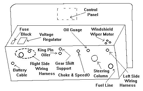
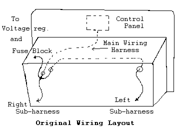
The wiring harness provides the electrical power to all the subsystems, and on the Morgan is composed of three sections. The first, largest, and most complicated was the front harness. This part contains all the wires for the switches and lights that are on the control panel of the dash board and the two front subharnesses. The right subharnesses connects to the voltage regulator, fuse box (such as it is), the headlight, parking light, brake light switch, starter solenoid, ignition coil and the turn signal on the right side of the car. The left subharness does the same thing on the left side of the car.
The second part of the harness is the connecting harness which connects to the main harness, to the rear harness, and runs down the right side of the passenger compartment to the rear fender arch. This harness contains all the wires to the rear of the car for the stop lights, turn signals, license plate light, and fuel gauge sending unit.
The third part of the harness is the rear harness which connects the connecting harness to the individual lights, etc. Each part of this wiring harness is covered in a cloth weave called a "loom". Before I continue with a discussion I should state that this rear part of the wiring harness should be in place BEFORE the rear deck (about 1/2 way down the article) is attached to the car. Otherwise trying to screw the clamps on to the wooden rear cross member is almost impossible.
To repair or make a wiring harness, you will be cutting and splicing wires and adding or replacing connectors. Therefore some knowledge of wire is needed.
Simplistic Wire Tutiorial
Very simplistic, wire comes in two basic types, stranded and solid. Solid wire has only one piece of wire the given size or gauge. Stranded wire, on the other hand, (you have 5 fingers, ha ha), is composed of many smaller wires twisted together. Due to the numerous individual strands, stranded wire is easier to bend and will withstand a lot more flexing than solid wire. This makes twisted wire the better choice for most automotive applications. However, it is more expensive than solid wire.The size or diameter of a wire determines its ability to carry current. The larger the diameter of the wire, the more current it can carry. Don't be fooled by looking at the insulation and thinking that a bigger wire will carry more current. The rubber or plastic insulation is just that an insulator. An insulator's job is to keep the current in the wire and not allowing the electrons to jump to the wire next to it or some other metal part (called shorting out).
Voltage is what determines the thickness of the insulation. The higher the voltage, the thicker the insulation must be. To demonstrate this principle, find and old spark plug wire and find a piece of wire from the wiring harness. Using a pair of dikes, cut both pieces of wire. Looking at a wire from the wiring harness, you will notice that the insulation is relatively thin. This is because most circuits on a car are only 12 volts. Now look at a spark plug wire. The actual wire is very thin and the insulation is very large. This is because these wires are carrying over 20,000 volts.
The following is a partial copper wiring chart which shows the current carrying capabilities of the various size wires.
              Wiring Table for Copper wire
          Wire Size           Dia.       Current
           (gauge)        (in inches)    (amps)
             10              .1019         33
             12              .0808         23
             14              .0641         17
             16              .0508         13
             18              .0403         10
I was looking for some type of wire gauge to tell you about, but could not find one. Therefore, to tell what size a wire is, you will need a wire stripper (usually under $5 and available a Radio Shack or any store that sells tools). To size a wire, start with the larger numbers and try to cut off a piece of insulation. If it doesn't come off, then you chose the wrong size. Keep getting smaller until the insulation is cut off. If the wire gets cut (ie. several strands come off with the insulation), you have guessed too small. Try using the next size larger and see if the insulation is cleanly cut.
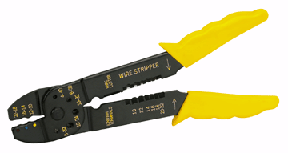 Wire Stripper/Crimper |
|
| The only nice thing that can be said about a wiring harness is that it is simple and requires only a couple of tools to work on it. The most important tool is a soldering iron. I have a constant temperature Weller soldering station I use for working on electronics equipment. However, a 40 watt, or greater, pencil can be purchased inexpensively. A soldering gun of the 100/140 watt pistol type can be used. (DO NOT try to use a | 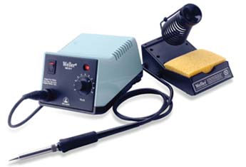 Solder Station |
 40W Solder Pencil |
propane torch with a soldering head.) A good quality rosin core solder is a MUST. A paste flux can also be used with the solder. DO NOT USE acid core solder such as used in plumbing as it will destroy the wire and the connectors. |
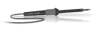
| A good pair of diagonal cutters (dikes) is also essential. (If you don't have a pair of dikes, I suggest you purchase a pair of 4 1/2" @ $8.59 and a pair of 7" wide-jaw @ $14 from Sears with their free replacement warranty. I've gone through 2 pairs of the 4 1/2" so far.) To strip the insulation off the end of a piece of wire, you can use a pair of wire strippers as described above, or a knife. However, I usually use | 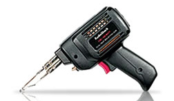 2 Temp. Solder Gun |
 4" Dikes |
A good pair of diagonal cutters (dikes) is also essential. (If you don't have a pair of dikes, I suggest you purchase a pair of 4 1/2" @ $8.59 and a pair of 7" wide-jaw @ $14 from Sears with their free replacement warranty. I've gone through 2 pairs of the 4 1/2" so far.) To strip the insulation off the end of a piece of wire, you can use a pair of wire strippers as described above, or a knife. |
| However, I usually use a razor blade. Most of the connectors used today are designed to be crimped on, consequently you will need a crimper. However, I do not like a connection that is only crimped. Therefore, I crimp the connectors with a pair of pliers, and solder each connector. For trouble shooting the electrical system, you will need some kind of voltage measuring device. A lot of mechanics use a circuit tester, a screwdriver looking tool with a wire coming out the handle and a light inside the handle, which cost under $5. I prefer to use a multimeter (voltage, current, and resistance meter) | 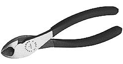 7" Dikes |
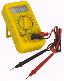 Digital Multimeter |
However, I usually use a razor blade. Most of the connectors used today are designed to be crimped on, consequently you will need a crimper. However, I do not like a connection that is only crimped. Therefore, I crimp the connectors with a pair of crimpers (show above), and solder each connector. For trouble shooting the electrical system, you will need some kind of voltage measuring device. A lot of mechanics use a circuit tester, a screwdriver looking tool with a wire coming out the handle and a light inside the handle, which cost under $5. I prefer to use a multimeter (voltage, current, and resistance meter) which is a more versatile tool and can be purchased for under $30. |
When I disassembled the car, the wires for each particular device
 (lights, wiper motor, horn, etc.) were disconnected, labeled and wrapped
with masking tape. The rear harness was removed first. Then the middle
section. Leaving the front main harness until last. When I started to
work on the wood and the firewall, I had to remove the front harness. I
started by pulling the left hand subharness back through the firewall.
Then to my amazement found out that it fed back through the firewall into
the engine compartment again as shown in the original wiring layout
drawing. At this point it joins the right subharness and the total harness
comes back through the firewall to the switch control panel! Once the
entire wiring harness was pulled back through the firewall, the 4 screws
attaching the control panel to the dash were removed and the entire mess
was placed in a box to be worked on later.
(lights, wiper motor, horn, etc.) were disconnected, labeled and wrapped
with masking tape. The rear harness was removed first. Then the middle
section. Leaving the front main harness until last. When I started to
work on the wood and the firewall, I had to remove the front harness. I
started by pulling the left hand subharness back through the firewall.
Then to my amazement found out that it fed back through the firewall into
the engine compartment again as shown in the original wiring layout
drawing. At this point it joins the right subharness and the total harness
comes back through the firewall to the switch control panel! Once the
entire wiring harness was pulled back through the firewall, the 4 screws
attaching the control panel to the dash were removed and the entire mess
was placed in a box to be worked on later.
When later finally came, the firewall had been striped and repainted and reinstalled on the chassis. It was time to decide what to do with the wiring harness. I found a source for a harness, Rhode Island Wiring Service Inc. They wanted about $600 (in 1991) for the three sections. I thought this was a bit steep. (Note: according to Dale Barry, a complete harness is available from the factory for about $100 (1992 dollar) - might be worth checking into. (ED. I later found a company British Wiring that had a harness for about $300 - 1993 dollars. They have a great product, and I finally purchased and installed one of their harnesses.) Don't forget the most obvious and cheapest route, make one yourself.
My loom was very dirty and rotted and would have to be replaced. But what about the actual wires? To examine them, I cut off some of the loom to reveal the wires. The rubber insulation on them must not be cracked and it must still be flexible. Since the insulation for my harness was not cracked and was still flexible, I decided to reuse the original wires. However, something would have to be done about the loom. Again Rhode Island Wiring Service Inc. would re-loom the old harness with the cotton weave, but at the time, I didn't have the money to buy a new harness or have the original one re-loomed, so I used the newer plastic loom to cover the old harness. (If you're looking for "originallity you'll need to get a new harness or have your old harness re-loomed.)
If your old wiring harness is not reusable you can make your own. It looks scary but it is actually fairly simple. Using the original harness and the wiring diagram, write down all the different colors, sizes and lengths of wire that are required. (Add a couple of feet to the lengths so you have some room to play around with different routing schemes.) Try to find the colored wire from an local automotive electrical shop. If you cannot find a supplier, Rhode Island Wiring should be able to supply the wire. While the electrical system doesn't care what color the wire is, I would NOT suggest using all the same color wire. This would make it very hard to identify or trace a particular wire in the future. In addition to the wire, keep track of the number and kind on connectors required. (Note: earlier, I stated the harness was 3 sections. If you are making your own harness, you can make the middle section part of the dash harness. This would eliminate one junction. There are 2 schools of thought on this. The first says - make things small and easily replaceable - then use the connectors. The other school says - every connection is a possible problem area - don't use the connectors. The choice is yours.) Once the supplies have been located, the wires are installed one wire at a time. More on this in a minute.
I started the reinstallation of the wiring harness by hanging the control panel from the wooden frame that the dashboard attaches to. Then I tried to reroute the wires the way they were originally run. The main harness, from the control panel, was inserted through the firewall. I had a rough time getting the large knot, that forms the Y for the harness to split, through the firewall. In fact working this Y through the firewall, chipped the paint around the hole. Consequently, I would surmise that the harness was installed by inserting it from the front of the firewall back into the cockpit. This would mean that all the wires would have to be disconnected from the stitches. Initially I was afraid to do this, as I didn't think I'd get all the wires hooked up correctly.
Once through the firewall, the right subharness was draped along the chassis, and the left subharness was threaded back through the firewall, across it, back out the left side of the firewall and laid along the left side of the chassis. I started to put some of the 1/2" plastic loom over the old cloth loom on the right subharness. As I worked form the front of the harness, back towards the firewall I could see that the Y was going to be impossible to cover with the plastic loom. In addition, the main trunk of the wiring harness was so large, I couldn't get plastic loom big enough to cover it. All this time, the cloth loom was falling apart. I finally decided to cut all the old cloth loom off the harness. Starting at the front, I used a small pair of diagonal cutters (dikes) to cut back the loom. Every time I came to a wire that branched off, I would wrap the bundle of wires with a piece of electrical tape on either side of the wire. This keeps the wiring harness intact. (Note: I tried using small nylon wire ties to hold the harness together, but their heads were too large to fit in the plastic loom.) When I started on the left side, I pulled the wiring harness back through the firewall so I could cut the loom all the way back.
I was now ready to run the wires back through the firewall. But I could not understand why all the wires for the left side of the car were threaded in and out of the firewall! There had to be a better way! So I threw caution to the wind, pulled the tape off all the wires and thought I could do a better job. Now I had what appeared to be a couple of hundred wires laying all over the floor and was beginning to wonder if I'd made a big mistake! How many beers had I really had?
At this point it was as if I was making my own wiring harness. Armed with the wiring diagram in, I started looking for a neater way to dress these wires. Since the wires were still attached to the switch, it was easy to validate the color code in the diagram. First I untangled the wires on the light switch. The wires going the left side of the car (having been threaded in and out of the firewall) would be longer than the wires for the right side. The wires for the headlights were routed across the underside of the dash to the dimmer switch. From the dimmer switch the left headlight's high and low beam wires were routed through the hole on the left side of the firewall. The wires for the right headlight were routed across the underside of the firewall and out the original hole on the right side of the fire wall. To start reforming the "new" wiring harness, as wires were identified and routed, they were wrapped with short pieces of electrical tape about every foot.
The wires for the sidelights (parking lights) were located. The longer one was bundled with the main headlight feed wire across the underside of the firewall and out the hole in the left side. The wires for the right side were feed through the hole in the right side of the fire wall and bundled with the headlight wires. The same thing was done with wires for the front turn signals. As each new wire was added, they were taped into the bundle.
Looking at the modified wiring layout diagram, notice that the hole
in the firewall, where the wires for the left side of the car were
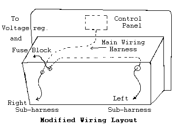 threaded back into car, is not being used. This would be a perfect place
to bring the wires that attached to the voltage regulator and the fuse
block through. Now there would be two smaller harness for the right side
instead of one large one. One by one, each wire for the front harness was
rerouted. As the new wires were added to the existing bundles, the old
tape was removed and the bundle retaped. Again as a wire reached its
break out location, the wiring harness was tapped each side of the wire.
After all the wires were connected, the plastic loom was installed. The
clamps that secure the wiring harness to the fire wall were installed
after the loom was installed.
threaded back into car, is not being used. This would be a perfect place
to bring the wires that attached to the voltage regulator and the fuse
block through. Now there would be two smaller harness for the right side
instead of one large one. One by one, each wire for the front harness was
rerouted. As the new wires were added to the existing bundles, the old
tape was removed and the bundle retaped. Again as a wire reached its
break out location, the wiring harness was tapped each side of the wire.
After all the wires were connected, the plastic loom was installed. The
clamps that secure the wiring harness to the fire wall were installed
after the loom was installed.
This process was not difficult, only tedious. I spent about 6 hours rerouting the wires.
Once everything was reconnected, I wanted to ensure that then I connected the battery the wiring harness would not go up in smoke. My car uses positive ground. This means that the positive side of the battery is connected to the chassis instead of the more conventional negative ground. To test the harness, all the switches were placed in the off position, and the low voltage wire to the coil was disconnected. The following two checks should be made with the multimeter:
- Connect the ground wire from the chassis to the battery (the positive terminal for a positive grounded car). A voltmeter (set to 12VDC) was then connected between the hot side of the battery (the negative terminal) and the battery cable. The meter should indicate 0 volts. If the needle tries to move to the left, reverse the multimeters leads and try again. A reading of 12 volts indicates that some circuit is activated or a short exists in the harness.
- With both cables for the battery disconnected from the battery, set the multimeter to the lowest resistance available, usually R X 1. This means that the meter is reading the actual resistance and you do not have to multiply the meters reading by anything.) Connect one lead from the meter to one of the main power cables, and then connect the other lead to the other power cable. The meter should not move, indicating very high or infinite resistance. The more the meter needle moves, the lower the resistance, indicating either some circuit is activated or there is a short in the wiring.
In closing, let me pass on a tip. When working with old wire, you will notice that when you strip back the insulation, the wire is dark, not shiny. This means that the wire has oxidized and the solder will not stick. To remove the oxidation, you can try either of two methods:
- Use some medium grit sandpaper (100 grit) and try to sand the wire shinny.
- Heat the bare wire with the soldering iron and then dip the end of the heated wire into some Tarnex. Just dipping the wire into the Tarnex without heating it will NOT do the trick.
- I found the best solution is to dip the wire into some phosophoric acid. You can get this either under the trade name Oshpo or DuPont's Metal Conditioner. I then dipped the wire in water to neutralize the acid and dryed the wire with a towel.
Enjoy your Morgan
John
Morgan Wiring Digram
Return to the Index of Tech. articles
To email me with comments or
questions.
Sheet 1 - Starting & Charging Diag.
Sheet 2 - Exterior lighting Diag.
Sheet 3 - Interior lighting Diag.
Sheet 4 - Fused items Diag.