by Dan Masters, danmas@aol.com
(ED. This article was originally post on Vintage Triumph Regesters web site. I've asked Dan if I could post it here as VTR has blocked their technical articles to nonmembers. Dan gave me permission on 10/02/06. )
WIPER OPERATION:
There are three major components to a wiper motor:
· Motor
· Rotary to linear motion converter mechanism
· Parking switch
The mechanism to convert rotary motion to linear motion is very straight forward, and its functionality is apparent from a visual inspection of a disassembled motor assembly. This article, therefore, will discuss only the operation of the motor and the park switch. Although written specifically for a TR6, it is typical for many later model British cars. A separate description is provided below for earlier models -- TR2, 3, 4, etc.
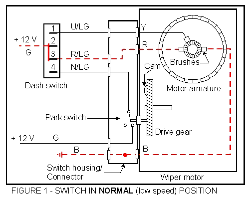
A) NORMAL OPERATION:
| Refer to Figure 1. In this mode of operation, the dash switch is in the normal, or low speed, position, and internally, terminal 2 of the switch is connected to terminal 3. Current flows through the motor as shown by the dotted red line. The operation of the parking switch has no effect in this mode, as terminal 4 of the dash switch is not connected to any other terminal. |
|
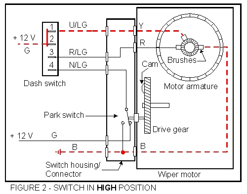
B) HIGH SPEED OPERATION:
| Refer to Figure 2. In this mode, the dash switch is in the high speed position, and current flow is as shown. This is basically the same configuration as the normal mode, except the power flows through the high speed brush rather than the normal speed brush. Internally, terminal 2 of the dash switch is connected to terminal 1. |
|
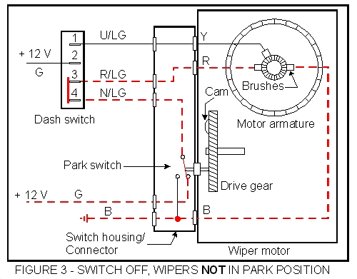
C) WIPERS OFF, BLADES NOT IN THE PARKED POSITION:
| Refer to figure 3. With the dash switch off, power is supplied to the motor through the contacts of the parking switch, and the motor continues to operate. Until the drive gear rotates to the point where the cam operates the switch plunger, the motor will operate at the normal, or low speed, just as if the dash switch were still on. |
|
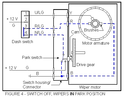
D) WIPERS OFF, BLADES IN THE PARKED POSITION:
| Refer to Figure 4. When the drive gear has rotated to the point that the blades are in their parked position, the cam button on the drive gear depresses the parking switch plunger, operating the switch. Now, rather than the 12 volts as before, ground is applied to the low speed brush, shorting out the armature windings. The magnetic field that had built up in the windings when 12 volts was applied will now discharge through the switch contacts, in very much the same manner as the operation of the primary windings in the ignition coil. This discharge current, shown as a dotted blue line, will be in the opposite direction as the normal current flow, and will tend to reverse the rotation of the motor. Because the windings are now short-circuited, the discharge takes place very quickly, and the reversing energy lasts just long enough to stop the motor. The energy in the discharge is such that the motor will stop immediately! In fact, if your are holding the motor while testing this operation, hold on tight, because it stops so quickly that it will jump out off your hand if you are not careful. |
|
TROUBLE SHOOTING:
A) WIPERS DON'T WORK AT ALL:
|
1) Verify that the problem is electrical, and not mechanical - binding in
the wiper wheel boxes, etc., before proceeding with the electrical tests.
This can be done by listening to the motor with the switch on. If it is a
mechanical problem, the motor will hum.
2) As with all electrical problems, the first step is to verify that all connections are good, and that there are no obvious breaks in the wiring. Repair or replace as needed. 3) If a visual check shows the wiring and connections to be OK, remove the fuse from position # 1 of the fuse box (white wires on one side, green on the other). Jumper from the brown wire on fuse # 2 to the green wire on fuse #1. Why? This has the same effect as turning on the ignition key, except the ignition (coil) itself is not energized. Normally, the ignition key connects the white wire to the aforementioned brown wire, which then feeds power to the accessories via the green wire. Jumpering from brown directly to green just bypasses the ignition switch. This is a good step for troubleshooting any electrical accessory that requires the key to be on to work. By pulling the fuse to the white wire, the points are not subjected to damage. 4) Remove the plug from the wiper motor. 5) Turn the wiper switch to the normal position, and check that 12 volts is present at the terminal with the R/LG wire. With the wiper switch in the high position, check for voltage at the terminal with the U/LG wire. Check for continuity to ground at the terminal with the black wire.
6) If there was no voltage present during step 5), with the dash switch in the normal position, test for voltage on the terminal of the dash switch with the R/LG wire. With the switch in the high speed position, check for voltage at the terminal with the U/LG wire.
7) If all tests in step 5) were satisfactory, then the wiper motor must be disassembled for further testing.
8) If needed, the dash switch can often be repaired. Using a small screwdriver or other tool, very carefully pry the case open. A close examination of the switch will reveal where to pry, and how the switch comes apart. Very carefully note the position of the contacts, springs, and other parts as you disassemble it. Clean the interior and all the parts. Lightly rub the contacts with a piece of emery cloth, or other abrasive (a pencil eraser works very well). Lubricate and reassemble. Check with your local electronic supply house for the appropriate lubricant. |
B) WIPERS WORK BUT WON'T PARK:
|
1) Perform steps 2) and 3) above.
2) Remove the plug from the wiper motor and check for voltage at the green wire. There should be voltage here at all times, whether the wiper switch is on or off.
3) Replace the plug and turn the dash switch to either the normal or the high-speed position. Check for voltage on the brown/light green wire. Voltage should be present at all times EXCEPT when the wiper blades are in their normal park position. That is, the voltage should turn off as the blades pass through the park position, and turn back on again as the blades leave the park position. There should be a long on, followed be a short off, long on, short off, etc. It may be difficult to measure the voltage on this wire. You may need to use a fine needle to pierce the insulation, and measure the voltage at the needle.
|
EARLIER MODELS:
Earlier models are a bit simpler than the later models, as you might expect. Power is applied to the wiper motor at all times when the ignition switch is on, and the motor is grounded by the operation of the dash switch. As soon as the wiper blades move to some position other than the park position, the parking switch inside the wiper applies ground to the motor. Thus, when the dash switch is turned off, the motor will continue to operate until the blades reach the park position. There is no field discharge current to assist the parking in this configuration, so the parking is not as crisp as in the later models.
WIPER OPERATION:
A) NORMAL OPERATION:
|
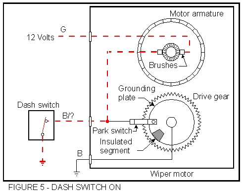
Refer to Figure 5. With the dash switch on, the motor windings are grounded,
and the wipers are operating. The position of the insulated segment with
respect to the park switch is immaterial, as the motor is already grounded
by the dash switch - if the wipers are not in the park position, the park
switch just provides an additional ground path. The current path in this
condition is shown by the dotted red lines.
Note: The park switch configuration is not as shown in the diagrams. In reality, the grounding plate with the insulated segment is fixed, while the park switch rotates with the drive gear. I just couldn't figure a good way to show that without a complicated drawing. |
|
B) WIPERS OFF, BLADES NOT IN THE PARK POSITION:
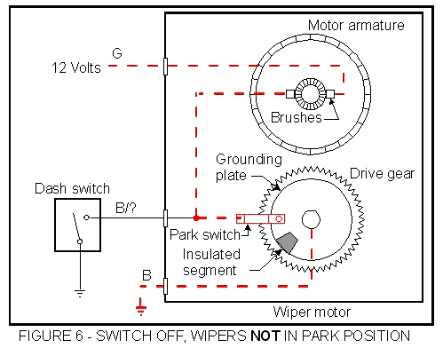
| Refer to Figure 6. With the dash switch off, the ground path is through the park switch. As long as the wipers are not parked, the motor will continue to run. The current path in this condition is shown by the dotted red lines. |
|
C) WIPER SWITCH OFF, WIPERS IN PARK POSITION.
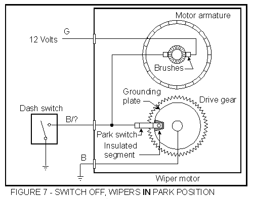
| Refer to Figure 7. With the dash switch off, and the park switch open, there is no ground path for the motor. When the park switch opens, the blade motion stops and the wipers are parked. |
|
TROUBLE SHOOTING:
A) WIPERS DON'T WORK AT ALL:
|
1) Verify that the problem is electrical, and not mechanical - binding in
the wiper wheel boxes, etc., before proceeding with the electrical tests.
This can be done by listening to the motor with the switch on. If it is a
mechanical problem, the motor will hum.
2) As with all electrical problems, the first step is to verify that all connections are good, and that there are no obvious breaks in the wiring. Repair or replace as needed. 3) If a visual check shows the wiring and connections to be OK, remove the fuse from the fuse box position that has white wires on one side and green wires on the other. Jumper from the brown wire at the fuse box to the green wires on fuse you just removed. If your particular model Triumph has no brown wire at the fuse box, jumper to the battery. Why do this? has the same effect as turning on the ignition key, except the ignition (coil) itself is not energized. Normally, the ignition key connects the white wire to the aforementioned brown wire, which then feeds power to the accessories via the green wire. Jumpering from brown directly to green just bypasses the ignition switch. This is a good step for troubleshooting any electrical accessory that requires the key to be on to work. By pulling the fuse to the white wire, the points are not subjected to damage. 4) Disconnect the wires from the wiper motor. With the dash switch on, check for the presence of 12 volts on the Green wire. Check for continuity to ground on the Black with colored stripe wire.
5) If all tests in step 4) were satisfactory, then the wiper motor must be disassembled for further testing.
|
WIPERS WORK BUT WON'T PARK:
|
1) Perform step 2) above.
2) Disconnect the black grounding wire from the wiper motor. Check for continuity to ground.
|
EMERGENCY SWITCH REPLACEMENT:
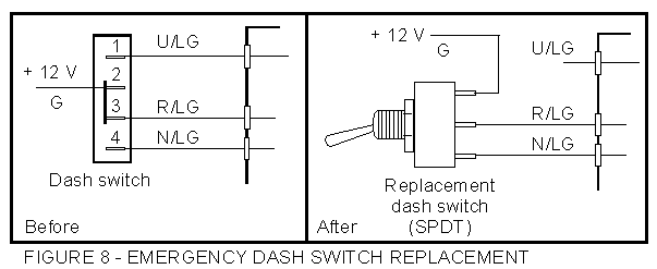
In an emergency, the dash switch can be replaced with a simple switch from Radio Shack, or similar supplier. For the earlier models, a simple on-off switch will do, wired directly as a replacement. For the later models, a SPDT switch is required to implement the parking function. Wire it as shown in Figure 8. Make sure the switches are rated at least 10 amp. For the SPDT switch, don't use the typical switch as found in most auto parts stores, as these nearly always have a "center off" position, ie, ON-OFF-ON. The switch required for application has only two positions: ON-OFF. This will only allow low speed operation, but that is preferable to no operation at all.
|
Return to the Index of Tech. articles
To email me with comments or questions.