 1133 Chatmoss Dr., Va. Beach, Va. 23464; (757) 495-8229
Written: Dec, 2008
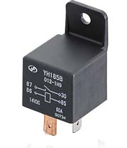
Bosh Type Auto Relay
The Basics
There are basically 4 parts to a relay:
1. The contacts - which are relatively large pieces of metal and form a switch. Their size is based on how much current the relay is to handle.
There are 2 types of contacts in a relay: the fixed and movable. The movable contact has some sort of spring, either a normal coil spring or a piece of spring metal that will move the contacts to the “resting” (non-energized) position. This position is called Normally Closed. The other position, it is called the Normally Open (NO). When the relay is energized the movable contacts move to contact the NO contacts.
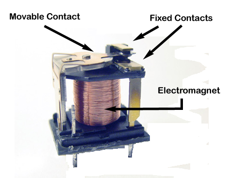
Relay Internals
3. Connections/pins to the relay. On the outside of the relay case are the connector pins that will allow the relay to be connected to the various wires of the circuits.
4. The case is used to cover the parts of the relay with the exception of the connection pins. These cases can be metal or plastic, and in some instances no case is used and may (or may not) have a mounting tap on it.
The NC connection may or may not have a connection to the outside of the relay. If it does, then the relay is called a Single Pull Double Through (SPDT) because there are two positions. If there is not a connection for this NC contact then the relay is called a Single Pull Single Through (SPSD).
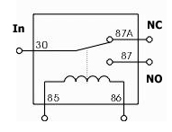
Schematic Symbol
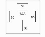
Pin Out
The high current side is comprised of Pins 30, 87A the Normally Closed (NC) contact, and pin 87 the Normally Open contact. To use the relay to turn something on, current will have to flow through the switch formed by pins 30 and 87. These 2 pins will only be connected when the trigger signal is applied to the coil.
In addition to controlling the horns and starter motor, other uses could be to remove high current from existing switches on the car, like the high speed high current for the heater blower motor (see “Meltdown in Arizona” by Steven Rhodes, in the July 2007 issue of The Brickline, page 12-16) or to remove the high current from the headlight switch, or to control an additional electric radiator fan.
The control side uses the on off switch to control the current to pin 85. When no current flows to pin 85 then the relay is in the off position and the light bulb is off. When the on/off switch is turned to the on position, current is allowed to flow to pin 85 and through the coil to pin 86 and to ground. Thus causing the electromagnet to pull the internal switch closed and connects pin 30 to 87 and the light bulb will turn on.
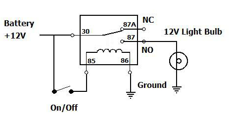
Simply Application to Turn on a Light Bulb
When looking for a relay, you have to know how much high current you need to handle. For example suppose that the light bulb in the above example draws 10 amps. So the relay should handle 20% to 50% over what is required. This is called a safety margin. So a relay with a rating of 15 to 20 amps, or going even larger is fine. Only the higher the current rating the more expensive the relay usually is.
You will have to know if you want an AC or a DC relay. For automotive uses we want a 12V DC relay, which these Bosh type relays are. They typically draw about 1/4 amp. through the coil. So we have 1/4 of an amp. controlling a 10 amp. load.
Typically a Bosh style 20A relay sells for $5 to $10 depending on where you get it and how many are purchased.
Troubleshooting:
There are two parts of the relay that can fail: the electromagnet or the contacts. Testing a relay can be done in place or when it is removed.
Since relays are inexpensive, the easiest way to test one is to simply replace it. If that doesn’t work, then there is a problem with something else in the circuit.
But you can test the relay.
To test the electromagnet’s coil in place, you will need to know how the relay is energized. It can be energized by applying power (+12V) to one side of the coil through a switch and have the other side of the coil grounded as in the sample circuit or power is applied all the time, and the ground side switched.
Test for power - Switched Power:
Assuming that the power (as in the sample circuit) is switched proceed to test the coil as follows:
For this test, it’s easier if the relay is pulled and you test the plug that the relay plugs into. Using a multimeter, set to 12VDC or higher, connect the negative lead to a good ground, usually any metal part of the car. Using the Positive lead, check to see if either pin 85 or 86 has power applied to it. If not, try to turn on the circuit, i.e. headlight switch, and check again. If no voltage is found on either pin, then there is a problem with the power supply to the relay’s coil.
Test for power - Switched Ground:
Is the same as in testing for power - Switched Power above, except you don’t have to turn anything on. Power is always applied to the relay. The ignition switch may have to be in the “Run” or “Aux” position.
Test for ground - Switched Power:
Be sure that the power is turned off (disconnect the battery) and using the multimeter set to the lowest resistance (R or Ohm) setting. Connect ground lead to a good ground. Connect the other lead to the pin 85 or 86 that should be grounded. The multimeter should read 0 Ohms. If not, there is a bad ground. You will need to check the ground connection or run a new ground wire.
Test for ground - Switched Ground:
For this test, you need to have tested for power and know which pin has power. You will need to have pulled the relay, and have the battery connected.
Do not connect the multimeter to the power pin! If you do, you can destroy the meter!
Using the multimeter set to the lowest resistance (R or Ohm) setting, connect ground lead to a good ground. Connect the other lead to the pin that did not have power to it. The multimeter should read 0 Ohms. If not, make sure that circuit is turned on. For instance, press the horn button. This will complete the ground circuit and the meter should show 0 ohms. If not, there is an open in this ground circuit.
Test the coil:
The coil of wire must be intact for the relay to work.
It will be easier if the relay is removed from the circuit. If testing “in circuit” be sure the power is turned off to the circuit (no 12V to either pin 85 or 86).
To test it, set the multimeter to the lowest resistance (R or Ohm) setting, connect one lead to pin 85 and the other lead to pin 86. It should read about 100 ohms. If the meter reads infinite, the coil is opened. If the coil reads about 0 Ohms then the coil is shorted. In either case, the relay will have to be replaced.
Testing Contacts - Out of circuit:
If the coil checks good, you should be able to hear a click from the relay when the circuit is turned on. This is the arm being pulled to the electromagnet and the contacts going from the NC to NO position. But are the contacts making contact?
In most cases, you can pull the relay from the circuit, and remove the cover. If the cover is plastic, there are several clips made into the case. Use a screwdriver to pry between the case and the base of the relay and pop the cover off the relay. If the case is metal, you’ll have to bend the tabs and remove the cover.
You can manually press the arm to make the contacts make. Using a multimeter, set to the lowest resistance (R or Ohm) setting, measure the resistance between pins 30 and 87. You should get 0 Ohms. If not, try cleaning the contacts using a piece of sand paper. Cut a piece of sandpaper, and fold it so it’s rough on both sides. Place it between the contacts, press the contacts closed and pull the sandpaper through the contacts. Check the resistance of the contacts again. If it is infinite, then one of the wires between the contact and the pins has probably broken and the relay will need to be replaced.
Testing Contacts - In circuit:
Usually pin 30 is the input side of the relay’s switch. You will need to test for voltage on that pin with the circuit turned off. Using a multimeter, set to 12VDC or higher, connect the negative lead to a good ground, usually any metal part of the car. Using the Positive lead, check to see if pin 30 has power applied to it. If so, pin 87 should not. Now energize the circuit. (You should be able to hear a click from the relay when the circuit is turned on.) Now check pin 87 to see if there is voltage there. If not, then the contacts are not closing properly. You can try and clean the contacts (as described above) or replace the relay.
Contacts welded:
If you find that a circuit controlled by a relay will not turn off, then chances are the contacts are stuck or welded together. To check this, you can either follow the “out of circuit” test, and you will find that the resistance between pins 30 and 87 is always 0 ohms. Or “in circuit” testing, will show that there is always 12V on both pins 30 and 87.
Conclusion:
A relay is an electromechanical device to let a small current control a lot larger current. They are simple, easy to use, and will last a long time. So don’t be afraid to use them.
Enjoy your Morgan
John
Return to the Index of Tech. articles
To email me with comments or questions.