If you have found that the upper horizontal firewall plate has rusted underneath the tool box area and cracked, then you have just discovered another somewhat popular idiosyncrasy that our Mogs got blessed with. Well, all is not lost and there is a simple (well, not that easy) and inexpensive way to solve this problem. Just replace the complete top plate. Voila!
For those of you who possess this lightheaded French attitude, I will continue. The plate will be replaced using 1/8 inch aluminum. Why aluminum? Because aluminum is the easiest and fastest metal to work with. Otherwise using steel and an acetylene torch would end up with possible warping of the plate if not heated uniformly and it takes a lot more skill and sweat that is unnecessary.
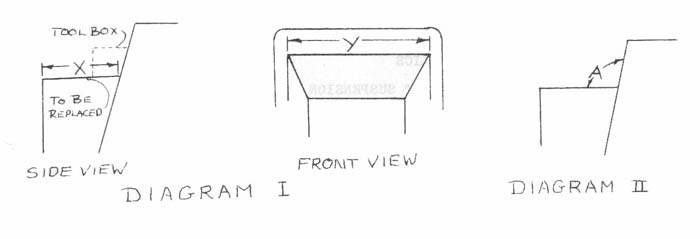
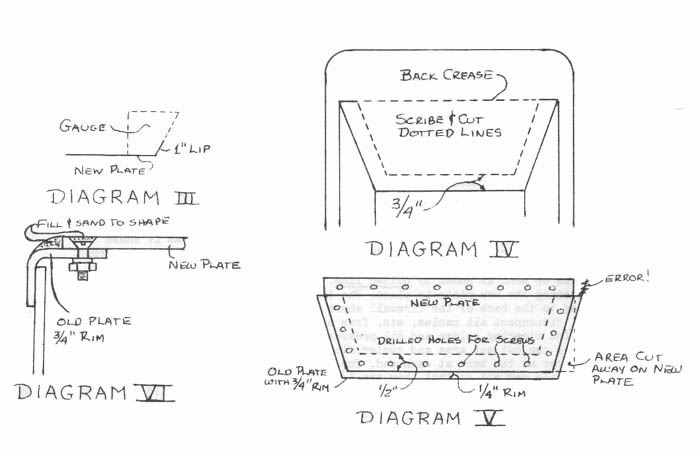
The first step is to unbolt the tool box on the plate and remove it so you can measure the distance "X" from the front edge to the back bend, as per diagram I. Add to this measurement 3/4 inch and this will be the width of the new plate. Then measure the distance "Y" and subtract 1/2 inch from the measure. mont and this will, be the length of the new plate. Secondly, an angular gauge must be made of the angle "A" that the top plate makes with the back firewall, as per diagram II. Use a piece of cardboard for this and save until later. Now, go out and purchase the aluminum plate and have it cut out to the measurements calculated earlier. Then take it to a metal shop and have them bend a 1 inch lip upwards until it matches the cardboard gauge you made earlier (make sure that the lip is is 1"- 1 1/16"). Now you should have a rectangular plate with a lip bent upwards along the length of it, as per diagram III.
The old plate should now be cut out. Scribe and cut out as the diagram IV shows with a hack-saw or sabre-saw after drilling holes to start the blade. The front three sides must have a 3/4 inch lip left and the back should be out right along the crease or bend as shown by the dotted line in diagram IV. The purpose of the 3/4 inch lip is for fastening the new plate in place. The 1 inch lip on the new plate is for fastening to the back of the firewall where you cut along the crease. Before cutting, disconnect all cable, etc. from underneath the old plate and watch out for the steering column and oil pressure line while cutting. Place the new plate over the cut out area and center along the back edge. It should be 1/4 inch shorter at the back at each end. The sides of the new plate will have to be marked now and cut so that they are 1/4 inch shorter on each side of the taper as shown in diagram V. Once the plate is properly cut it should fit as in diagram V and can now be drilled and fastened. The holes should be drilled so they are centered in the old plate's lip left underneath as shown in diagram V and through the lip at the new plate in the back so they penetrate the back wall above the crease. The type of fasteners used will be flat-head machine screws so that the holes should be drilled and counter-sunk allowing the screw heads to sit below the surface of the new plate. Screw the plate into place at this time. Body putty or plastic should be used to cover the tops of the machine screws. Remember, use flat-head machine screws that have a lockwasher and nut, do not use sheet-metal screws! Now we take the body putty or plastic and form rounded edges on the front three sides, not on the back lip, as shown in diagram VI to match the existing rounded edges of the old plate as shown in VI.
Completion is simple: sand body putty areas smooth, prime with spray cans, paint with spray cans, allow to dry and re-drill any mounting holes that are necessary. Re-install the tool box with the inside rubber matting and your new plate is completed! Q.E.D.
FITTING THE WINGS
by S. Stierman 69 +8
Fitting wings is not that difficult of job, it's not rocket science (assuming you know what end of a screwdriver to use).
The wing should be clamped to the valence under the radiator cowl and tucked under the body along the sill. Some trimming maybe needed along the front edge of this part so that the wings slide under the body. The bonnet should close with some gap between the wing and bonnet edge. Don't cut, drill, or bend anything till you establish an overall fit up of the complete assembly.
They will not fall right into place. By gradually tightening up the mounting screws on the valences, sills and bottom of rear wings, they will gradually pull into place. The hole you drill for the wing lamp to the brace should be the last you drill, and put some rubber between the bracket and the wing so that the bracket does not contact the wing at all.
Comments from John Blair
Test fit the entire front assembly - the firewall, valences, nose, wings, and hood. When you think every thing is OK then you can start to drill and bolt things up.
Also, don't know what or how you plan on marking the holes in the fender to drill. I assume that your valances are drilled on the top for the fender. There are a couple of ways of marking the holes on the fender to match the holes on the valances.
1. Get a "transfer punch" set. Transfer punches are rods the diameter of the hole you want to drill, with a point in the center. So as the transfer punch is set in the hole, the point should mark "dead center" on the mating panel.
2. I just went through this on my Bricklin. I have body skins to pop rivet and glue to the steel members. The steel members are already drilled, but the holes don't go all the way through the tubing so trying to find the holes when you lay the skin on is difficult. A friend described a tool that the racers use. Basically 2 strips of metal. Cut 2 pieces of metal about 1" wide and 6" long. I used about .060" thick metal. Stack them on top of each other and clamp. Drill pilot holes through both pieces at both ends of the metal (about 1/2" in or so). At one end, pop rivet the 2 pieces together. At the other end. drill a hole (for the size of bolt or rivit that will hold the skin to the frame). No put a bolt through that hole in the metal strip and weld the head to the metal strip and grind off most of the head.
To find the hole, insert the bolt (pin) under the upper
panel (ie skin) and set the top metal strip on the outter piece to
find the hole. Since both the pin hole and the pilot hole were d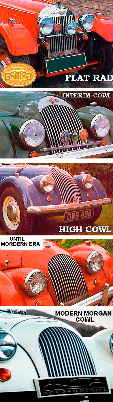 rilled
at the same time, they are perfectly centered on each other. No using
a centerpunch simply put it in the pilot hole of the top metal strip and
mark the place to drill.
rilled
at the same time, they are perfectly centered on each other. No using
a centerpunch simply put it in the pilot hole of the top metal strip and
mark the place to drill.
Comments from Bob Noguiera
1. The inner section of the wing that hosts the headlight bucket (not the section over the tire) is a much heavier gauge steel that the section over the wheel. You will need heavy duty cutters to do any trimming.
2. Be sure to fit the fenders with the bonnet in place. The BIGGEST problem is always getting the bonnet to fit so you have even gaps and no rubbing. The mounting of the fenders effect the fit of the bonnet.
COWL VARIATIONS AND FITTING |
WATCHPOINT: When
re-fitting the cowl when the wings and the cross bar have not been
removed, I attach it with two screws on each side (4 total) with the
bonnet attached fore and aft. I then make adjustments to achieve a
perfect fit with all this in place. I then do a final confirmation by
closing and latching the bonnet before I strongly tighten the four
screws and add the other 6 cowl screws. In recent years, Morgan has reduced their labor time by reducing the number of screws, one of the MANY efforts of the Factory in recent years, to lower manufacturing costs by degrading the quality of the car. The process is called hidden inflation by modern economists, which I was. The full extent of it can only be detected by those familiar with the original car's mechanical design. Many new owner complaints can be traced to this process and its consequences. Classic Morgans, at their best, were an deeply labor-intensive process. The company has tried its utmost to reduce this, like so many other manufacturers and products.  |
In the 50's and 60's, a metal strip was used to cosmetically cover the meeting of two panels, the rear spare panel and the side panel or quarter panel just above the rear wing and beading, by using a half-round piece. It was only an inexpensive cosmetic fix as Morgan was a lower-end priced sports car in those days. There were problems.
Over time the strip would rub through the finish and rust would appear. Also was two disimilar metals in contact causing a corrosive reaction. The scews were "filled in " to hide them and the meant no easy repair was possible. As time went on in the 70's the rear panel over-lapped 90 degrees into the sides to meet the rear wings thus eliminating this trim strip. But as a purist, what can one do with them now?
The strips are available in stainless and alloy which is softer and easy to shape. The under side of these strips are under-cut or half-rounded to clear nails or screw heads.Today's paints are more durable and less brittle than those decades. Some like to leave these strips unpainted as an accent. It's a personal thing to decide. The strips can be found still at Morgans or try a boat builder supply and they now call it Rub-rail and it must be purchased in fair quantity unless you are a charmer.