Rack
& Pinion Steering
by Lorne Goldman
Safety
Every vehicle has the
same
three systems that are life sensitive.
These are tyres, the brakes and the steering. There can be no
compromises with ANY of them. Happily, Morgan classics, (at least
they were ended) are wondrously simple areas and the task to keep these
areas safe is not difficult or
cumbersome.
Morgans get silly (and have owners react the same way) when elementary
maintenance is not done. AND I cannot over-emphasize the need for
vigilance or the dangers
of getting the wrong advice (I have seen some horrid examples of the latter in the last decade!)
If you have any doubts whatsoever, consult an experienced Morgan dealer.
Happily, the key watchpoints are SO simple that common sense should
warn you away from any advice you cannot immediately judge as correct at
a glance, whether you are mechanically enabled or not.
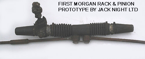
History
In 1983,
the Morgan Motor Company approached Jack Knight Ltd., a noted British aftermarket
steering specialist, to design a rack and pinion steering system for the
Plus 8, the heaviest of the model line-up and accordingly the most in need
of a steering improvement. The resultant rack was a great step forward
and was first offered in 1984 as an optional extra at £250. It became
standard on all Plus 8s by 1986, unless a customer was crazy enough to
ask for the older system. By 1991, it became a free option for Plus 4s
and by the mid-1990s it was standard on all Morgans.
Though
the design falls far short of an ideal in areas, it is a vast improvement
on previous Morgan steering systems and has three great virtues; it is
simple, it is solid, (save for one BIG watchpoint) and it fits on the Morgan front end. There is little
that go wrong with it outside of the most basic human errors in fitting
and checking it. On 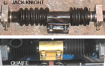 very rare occasion it can require adjustment,
which
is dealt with by David Poole in his great eMog posting, and after much mileage
the rack channel and spacers may require redressing, and easy job for any
machine shop. I have had a full refurbishing done in the UK for 75£s;.
very rare occasion it can require adjustment,
which
is dealt with by David Poole in his great eMog posting, and after much mileage
the rack channel and spacers may require redressing, and easy job for any
machine shop. I have had a full refurbishing done in the UK for 75£s;.
The Morgan
Motor Company had the stock rack's turns-to-lock changed a number
of times during its history.
In 2007,
the original Jack Knight company fell into bankruptcy and the MMC asked
Quaife Engineering to supply the rack. For all intents and purposes, the
Quaife Morgan racks are the same and can be retrofitted to Jack Knight
cars. The Quaife racks can be distinguished only
by their different centre gaiters, a big improvement over the Jack Knight
gaiter. However, Jack Knight
has been reborn under the management of its former employees and an upgraded
gaiter, as good as the Quaife gaiter, can be had from them if you can get
them to call back.
The old style JK gaiter is
flimsy and inexplicably expensive, by a factor of 5 to 10 times. The flimsiness bothers more than the price. Once they are torn (a MOT issue), the wisest course
is to replace them with the new JK gaiter which is as good as the Quaife.
(The Quaife gaiter will not fit a Jack Knight rack.) Quaife parts can
only be ordered through the MMC, Jack Knight parts can be ordered from
Jack Knight directly, if you can find them. However, the parts in each are generic and can easily be found in the UK
|
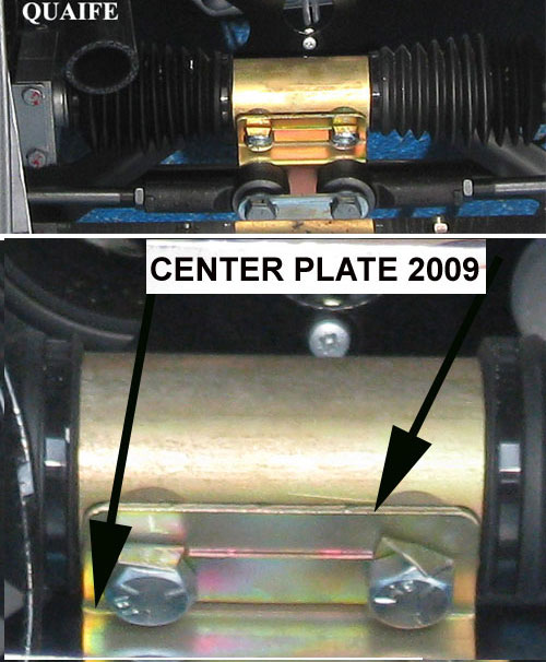
WATCHPOINT
Tierods-to-Center-Plate Any time the tie rods are removed from the steering rack center plate,
the steering alignment should be verified. This is made more important
if the plate itself is removed and even doubled again if both clamps holding
the rack to the crossframe are removed, (Though this is not strictly necessary
to change the gaiter, many take both clamps off to remove the whole assembly.)
All or most of this must be done simply to change the center gaiter. The
play at each junction is sufficient to through your steering out of alignment.
Trust ME on this and not your local non-Morgan mechanic. Many owners have
found the steering canting off one way or another after a gaiter change.
|
Morgan Steering Rack Types
by Lorne Goldman
The Morgan steering
racks are produced by;
| YEARS |
1983
to 2007 |
2007
to date
|
| TYPE |
Jack Knight Engineering
(UK) |
|
| SOURCING |
will repair
and sell Morgan racks direct, multiple options for turns-to-lock
|
will not
sell Morgan rack direct
|
Please note that
neither of these Morgan Steering Racks are advanced rocket science. It is their saving grace. I have
had them fully rebuilt and/or repaired by a number of machinists or
specialists, at a small fraction of the price that either of these two
sources (or their agent, the Morgan Factory) insist on. Aside from the
major components (the rack and its pinion), their parts are commonly
available.
Turns Lock-to-Lock
The
steering wheel lock-to-lock is the number of turns it takes for a
driver to get his steering wheel from its limit on one side to the
limit truned to the other side. Morgan changed these often
and Jack Knight offers many options.
Why is this important? The number of turns creates a mechanical ratio
that can help the driver with turning ease. The higher the number of
turns makes it easier to move the tie-rods the required amount to turn
at a certain angle. In other words, more turns lock-to-lock increases
the ease of turning the steering wheel at low to very low
speed, making it easier to park. Effort is only key at very low speeds.
On the other hand, fewer turns lock-to-lock makes the car more
sensitive to the steering wheel as it takes relatively less steering
wheel rotation to achieve movement to
They lesser the number of turns it takes, the
more sensitive the steering wheel is. Sensitive steering wheels provide
better responsiveness to steering inputs even at high speeds and driving
becomes instinctive. It's a simple result of mechanical advantage. The higher the ratio
(numerically), the easier it is to move the wheel, and more input at the
wheel is needed to move the tie rods a specific amount. That means
more steering wheel correction is needed when driving.
At the same time, too much wheel
sensitivity will make a car twitchy and hard to control. It's a very
fine balance that car makers and hobbyist owners have to deal with.
Changing the Jack Knight Center Gaiter (in 11 easy steps)
;)
by Lorne Goldman
If
you can, the gaiter is best changed with the rack in situ and wheels on
the ground. This may sound nutty, but if the rack is removed, it requires
so many items to be uninstalled that a full alignment and steering wheel
adjustment will be compulsory. This method will minimize the wheel alignment
issues when you re-assemble. If you raise the car, then try to brace the
wheels so that their relationship with the rack does not change during
the process. Secondly,
the gaiter CAN be changed with the rack in situ, no need to remove the
whole thing unless you really want to. With a RHD you can slip it
over the rack from the right hand side (as you are looking at the rack
from the front of the car) and the from the other side with a LHD.
For those who wish to remove the rack,
this can be done by removing the steering column at the rack rear and then
removing the two block brackets holding the rack to the crossframe.
1.
Open the lock tabs on the steering center plate, and unbolt the tie-rods
from the center plate (you will need a spanner to hold the nuts from the
back)
2. Let the tierods fall to the floor and
do NOT move them
3. Open the second set of lock tabs
and unbolt the center plate from the rack.
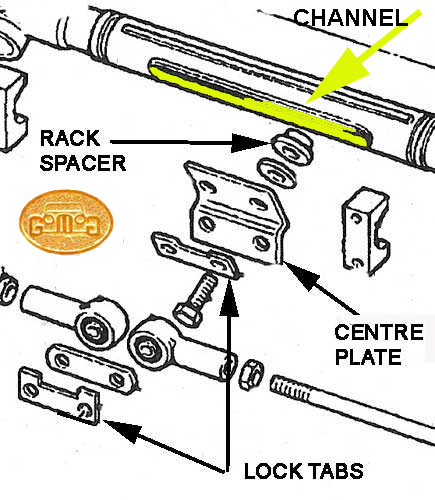
WATCHPOINT
I: The center-plate-to-rack bolts go through two spacers that slide
in the rack. They are not visible as the gaiters hide them. They create
a snug fit in the channel, reduce the amount of horizontal play, which
in turn, steadies the entire steering, (ANY BIT OF MOVEMENT HERE WILL BE
MULTIPLIED BY THE LENGTH OF THE STEERING COLUMN BEFORE IT REACHES THE STEERING
WHEEL). More on this latter.
|
| WATCHPOINT
II: These rack
spacers are designed to serve another purpose. They protect the gaiter
at its weakest point. If you look closely, (when you can examine the spacers)
you will notice thatt they have a small raised circlet in their metal on
the side that faces the bolt entry. This raised area goes into the two
gaiter bolt holes and prevents the bolts from crushing the gaiter and splitting
it..as the split will grow over time. If you are not
aware of this, the overwhelming possibility is that you split the gaiter
at these points and yet pat yourself in the head for a "job well done". Owners
do it, dealers do it, and it is very sad event at 60
quid a pop. |
4.
Now you remove the the bolts from the right side aluminum block holding
the rack to the crossframe, split it into its two pieces with a light hammer
tap if necessary. You can cut (knife or scissors) the old gaiter from the
rack or slide it off the right side you opened up. Watch for the spacers
to fall out.
5.
Now, test something. Can you squeeze the oily spacers through the bolt
holes in the gaiter? You should be able to and I want you to be confident
of that. Next slide the new gaiter back onto the rack, like you were putting
nylons on your favorite lady (or man). Be careful not to snag it but it
will adapt and stretch. You want its front (the center section with the
two holes) to be facing forward and you want the two spacers to be in the
correct position in the channel and facing forward. Fiddling will be involved..a
Morgan tradition!
6.
Now fiddle in the plate-to-rack bolts. You must align the bolts, the lock
tabs, the gaiter bolt holes, the spacers and threaded holes in the rack
pinion..a screw drivers and you no-oily fingers can be used. Get each one
threaded loosely before you tighten anything. Please don''t forget anything
or their order. You do NOT want to get me upset.
7.
Once you tightened the bolts, lock the tabs. Only one bit need be touching
each bolts.
8.
Re-install the aluminum block on the right attaching the rack to the crossframe.
9.
Forget the silly metal bands they used to clamp the gaiter, use the
right-sized tie wrap and trim off the ends.
10.
Then put on the tie-rods, this might require you to move the center plate
along the rack. It is better to move the rack than the rods. Now
close their lack tabs. Now get a bit of oil paint and make reference lines
from a corner of each of the four bolts. In the future, these lines will
allow you to see if any of these all important bolts have shifted at a
quick glance.
1.
The trick with the end cones is that people slide them on too far. First
deep turn and they pierce the cone with the rack without knowing it. The
rack does not require much lubrication. Almost anything will do, hypoy
oil (like you use in the axle) or chain saw oil or use the silly GoMoG
Manual https://www.gomog.com/allmorgan/r&p.html#lubricant
. Jack the car front on one side so it is atilt. Remove the cone. Fill
it up and fit it back on. Tie-wrap it. As you have taken the whole
center gaiter off, do it on the other side as well.
Otherwise, topping up one side is sufficent for maintenance purposes.
| WATCHPOINT
III: Yes. You're right. The JK gaiter is a fright. It is a flimsy
affair made by laminating (coating) silicone on a form. It is nowhere
near the quality of similar gaiters and its price is a function of
insane greed. ;) Jack Knight no longer supplies them.. I have heard they are
now made for Morgan directly by the old JK supplier. There are those looking
into a higher quality gaiter, easily sourced and reasonably priced. Perhaps
that will shame the company into being kinder. However, for those
of us in the UK, it is also a cause of a MOT failure. The examiners are
not happy with lubricant leaks next to disc brakes. So,
if you have one, do not demonstrate
your one-shot oiler to them either!!! |
|
 WATCHPOINT IV - PLAY
AT THE STEERING WHEEL WATCHPOINT IV - PLAY
AT THE STEERING WHEEL
Morgan rack and pinion steering
systems should have NO play at the steering wheel. None. There are a number
of causes for play, but the most dangerous ones relate to the fitting of
the rack and its tie-rods. Be aware that the length of the steering column
will exaggerate any rack anomaly at the steering wheel. making the steering
wheel your best early warning system. As soon as play is noticed, three
areas MUST be checked before driving further.
1. the two bolts holding
the centre plate to the steering rack itself.
2. the two bolts holding
the tie-rods (those rods which connect the steering rack to the front stub
axles and therefore the wheels) to the steering rack centre plate.
3. the four bolts (2 each
side) running through the two blocks that hold the rack to the car frame.
(Consult the diagrams here).
Between
1-3 the rack is held to the car and the wheels to the rack. If they are
compromised, so is your steering and your safety. At one time or another,
I have seen each of these areas with loose bolts. Care can prevent this.
Many times a visual test
will locate the problem.especially if one removes the centre gaiter. To test, have someone at the steering wheel and
have them turn the wheel while you look at the three areas, #2 will be
difficult as the bolts are obscured by the #1 bolts. Do it with the front
tyres on the ground and then again with them off. The rack should NOT move
on the frame and the only movement of the rods should be from side to side. However..read here.
|
WATCHPOINT V- CENTRE PLATE
TO RACK
These two bolts go through
a lock tab, the centre plate, often a small washer and then through the
important rack spacers (that keep the assembly guided within the parameters
of the channel in the rack) and then thread into the pinion. Obviously,
if these bolts come loose, the rack is no longer fully secures the centre
plate and therefore the tierods. Effectively, the steering wheel is losing
its connection with the front wheels. There are supposed to be secured
by the lock tab..but this can be left off by forgetfulness, or the tabs
can be forgotten (not closed), or have a insufficient contact with the
bolts.)
It is hard to perfectly
ascertain the state as the tierods cover these bolts. The centre plate
tierod bolts, must be removed and the tierods moved away top allow these
inner bolts to be examined. Once this is done, pull back the tabs and try
to tighten the two bolts. Once tightened, carefully bend back the tabs.
|
| WATCHPOINT VI Use a white paint marker
to draw a reference line from a point on each bolt to places on the plate
of your choosing. This reference line will make future examinations easy
as you will know in an instant if the bolt has moved if the line on the
bolt and the plate are no longer aligned. |
| WATCHPOINT VII Wheel Alignment. If you remove the
bolts entirely, you will have to reposition them through the gaiter and
then the spacers (by fiddling with the spacers) and then find the correct
holes in the pinion. This will almost certainly change the alignment. Have it checked. |
| WATCHPOINT VIII With
the older style Jack Knight gaiters (approximately 8000 Morgans from 1984
to 2007), close examination will show that the spacer has a round raised
area or that there is a small washer between the centre plate and the gaiter.
This was done to match the holes in the gaiter for the bolts. Without the
raised area or CORRECT sized washer, the plate will clamp the silicone
gaiter and the gaiter will split. If you replace your spacers. |
|
WATCHPOINT VI- TIERODS
TO CENTRE PLATE If you have properly dealt
with the Centre Plate to Rack bolts, you have removed the tierods from
the centre plate. Simply reassemble these, tighten and lock them with the
tabs. Use the paint mark system on these bolts
as well.
|
|
WATCHPOINT VII- BOLTS
THROUGH THE SECURING BLOCKS
Simple. There are two sets
of 2 half blocks that secure the rack to two L brackets on the car's crossframe.
(See the diagram above indicating "rack holder" & cross frame".) Each
half block has a half round centre that together match the rack and two
high grade long bolts going though the two halves into the L brackets.
When assembled the blocks clamp the rack onto the brackets and the frame.
If the bolts loosen, the rack loosens and moves askew with steering and
road anomalies. If the bolts fall out...
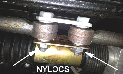
Check whether they are tight.
In the normal course, these bolts should not loosen as they are held with
nylocs. However, negligence is always possible and the re-use of nylocs
leads to their losing their ability to lock. One can use new nylocs, or
a bit of loctite blue or ultimately, stover nuts instead of nylocs. If
there is concern, use the same white line reference discussed above.
|
Lubricants
The approved lubricant (which was used in manufacture) is BP Energrease
FG 00-EP since it is a compatible with the application and gaiter material. By 2013 it was no longer available.
Here are alternatives.
Mobil Mobilux 2
SKF Alfalub LGMT
Shell Alvania R2 or G2
Esso Beacon 2
Actually..this
is for very anal sorts. I use any appropriate lube I have around. In my
case, in the Quebec mountains, it is chainsaw oil.
Adjusting
the Jack Knight Rack & Pinion Steering Rack
by David Poole at
the eMog
Pub
The rack is/was produced by Jack
Knight Engineering (UK) which now seems defunct
The following procedure should
be used to adjust the steering rack. There is no specified torque
setting for the adjustment locknut and the manufacturers specify that it
should be tightened “sufficiently to lock the adjuster in place”.
1. Thoroughly clean the area
around the adjustment assembly.
2. Remove the locknut, and
remove and discard the lock washer.
3. If the rack has a significant
mileage, unscrew the adjuster and remove it, together with the nylon follower
and spring.
4. Check that the nylon follower
is free to move within the bore of the adjuster, and that it is not damaged
or worn. If it is, replace it.
5. Replace the nylon follower
in the groove at the rear of the rack, followed by the spring and adjuster.
6. Gently screw in the adjuster
until it bottoms as it makes contact with the rack, and then unscrew it
¼ turn.
7. Place a new lock washer
over the adjuster, with the internal tongue engaged in the rebate on the
side of the adjuster, and the concave side down.
8. Hold the lock washer and
do up the locknut finger tight. Make sure that the adjuster does
not move.
9. Bend the outer tab of
the lock washer that is aligned with the gap at the front surface of the
rack towards the rack housing, so that it that locks the adjuster to the
rack body.
10. Tighten the locknut sufficiently
to lock the adjuster in place, and bend one of the tabs on the lock washer
away from the rack housing and over a flat on the nut.
LUBRICANT
The approved lubricant (which
is used in manufacture) is BP Energrease FG 00-EP since it is a compatible
with the application and gaiter material. The specifications for
the grease are defined below.
BP Energrease FG 00-EP
- Description
Energrease FG 00-EP is a
mineral oil based, polymer-thickened, stable, semi-fluid gear grease. It
contains an anti-oxidant additive and also a sulphur-phosphorous type EP
(extreme pressure) additive. It has excellent shear stability, load-carrying
ability and the coating characteristics that eliminate the risk of dry
start-up.
Application
This grease has been satisfactorily
used by many industries overseas and in South Africa in enclosed spur,
bevel, helical and worm gearboxes. The operating temperature range is -10°C
to 100°C.
Advantages
- Overcomes leakage of lubricant.
- Suitable for a wide range
of gearbox applications, irrespective of the attitude in which the gearbox
is mounted
- Eliminates dry start-up
- Allows extended maintenance
periods
- Exhibits excellent shear
stability, oxidation stability and load carrying ability
- Reduces noise
- Improves reliability
|
| N.B. Adjustment of the rack & pinion
is a rare procedure. Most racks are well set-up at the outset and will
stay that way for many years. Check other area for vibration first and
the bolts holding the rack and those to the center affixing plate. |
WATCHPOINT: On more used R&P Morgans, there
will be wear in the centre of the rack channel which will increase over time. My Jack Knight produced a steering wheel vibration and an up-and-down movement after
37,000kms (23,000 miles) and its seems Quaifes are exhibitting the same
issue. If the play is not attended to or the waer accelerates with the
movement that the owners are tolerating. In a bit, the feedback gets
worse and the rack is unrepairable. This was mentioned on a
mechanically-challenged UK forum but those who noticed it did not
investigate or even remove the gairter hiding the problem area. That
has many owners buy a new rack for
astronomical prices. (Morgan, though they abandonned this steering system (Jack KNight & Quaife) in 2019, the MMC still
has an exclusive with Quaife that prevents Quaife from selling to us
and many Quaife fitted cars are have wearing r&ps by now.
That keeps Morgans profit intact. R&P systems, generic or
otherwise, normally cost 20% of what MMC charge. The far more expensive
new cars (the Plus Four and Six, use these!
However, this wear can be dealt with for very little and
a 30 minute wait (my outlay was a 6 pack of beer) if you have a
decent machine shop nearby. I merely told him to widen the channel a
bit to even it out again and create spacers with a larger outer
diameter to fit as snuggly as the original spacer. That eliminated the
up and down movement and the vibration. It saves an owner many
hundreds, and after, all this is going to be happening again. The
current MMC has boasted that the new Morgans contain only 1.6% of the
components used in the cars up to 2020. Considering the MMC quickly
abandons support of non-current production within a VERY short
time..since the advent of the first Aero. it is prudent to either
stockpile parts you will need in the furture while you can, OR learn how to repair your Morgan.
SEE HERE.
|
Comparing the Jack Knight & Quaife Steering Racks
by
Lorne Goldman 2014
 In
1983, Maurice Owen, the Morgan design chief, approached Jack Knight, a
small lot UK designer of automobile parts, to design a rack & pinion
steering system for the Morgan Motor Company. The first was fit, as an
option, in 1983. Some 24 years later in 2007, Jack Knight ran into business
problems suspended affairs for a time. Morgan approached Quaife Ltd, used for some Three Wheeler parts, to
provide a replacement. The newer Quaife unit can be swapped in, without
undue fiddling, to replace a Jack Knight. And the reverse will be true
as well. In recent years, Jack Knight returned to business under some former
employees and has become reliable supplier. That gives owners two options
for their Morgan R&P replacement or special needs.
In
1983, Maurice Owen, the Morgan design chief, approached Jack Knight, a
small lot UK designer of automobile parts, to design a rack & pinion
steering system for the Morgan Motor Company. The first was fit, as an
option, in 1983. Some 24 years later in 2007, Jack Knight ran into business
problems suspended affairs for a time. Morgan approached Quaife Ltd, used for some Three Wheeler parts, to
provide a replacement. The newer Quaife unit can be swapped in, without
undue fiddling, to replace a Jack Knight. And the reverse will be true
as well. In recent years, Jack Knight returned to business under some former
employees and has become reliable supplier. That gives owners two options
for their Morgan R&P replacement or special needs.
Being
interchangeable, it is an excellent time for a review and comparison to
help owners choose if a need presents itself.
Firstly,
both racks are very simple and solidly made. I have never heard of a
Jack Knight (JK) or a Quaife (Q) failure and if someone out there has..please
write
me. Ergo, there is
no known difference in reliability. Amongst
other JKs, I have my original 1984 in spares. At 100,000 miles (with my
first Morgan) I did have to straighten the pinion passage and make two
new spacers to match the widened passage but other than that, it served
me without a problem for over 150,000 miles. However, Qs have
presented no issues either in
the seven years (at the time of this writing) they have been around. I
know only of one failure and it was attached to a bent crossframe.
Of
course, there is a lot of lore available for the JK and none for the Q
as yet. The Q is a factory part and the Morgan world is therefore not informed
of much from them these days. However, the similarities between the two units are
such that a Quaife should not be a problem for a skilled amateur or machinist
to deal with..and that is unlikely to be necessary.
Quaife
Ltd will not supply the the rack to anyone other than Morgan. However,
Jack Knight has lost its Morgan trade and like many of former Morgan suppliers
in that position, they now supply the community direct. Though the quality
of the two racks is comparable, JK units can be had at a fraction of the
Quaife cost, and if JK has its act together when you call, you will receive
it in much less time. (They now have a well laid out web
site with online buying.
Quaife
comes in one version..3 turns to lock. A Jack Knight R&P can be had in many
versions to better suit each driver, 2.3, 2.7, 3.0 or 3.5.
And for the many Superform
wing cars where the front wheels rub and blister the paint, Jack Knight
can customize a rack to prevent the wheels from doing so.
A JK can also be easily converted from RHD to LHD or vice
versa. We are told that, so far, the Quaife cannot be converted. That doubles
the potential market for a JK over a Quaife. N.B.
Morgan's new dealership
contract prevents dealers from selling any other rack than a Quaife.
July 2020. I have the necessary information now to write and article on
how to do the swap. Watch this space.
One advantage of the Quaife over the JK is the gaiter. Morgan
used a flimsy silcone gaiter for the JK for many years. They can split
if you stare angrily at them! (wry smile) Quaife's come with a large metal
center plate and gaiters that are tougher. However, Jack Knight designed
a similar gaiter to that of Quaife for their units. I suggest you buy it for your
JK, (if you can find and convince JK to produce one for you.
R&P Watchpoint
(1984 - present) Updated January 5, 2018
Revisited 2023
from Lorne Goldman on Morgan Addicts
THE TWO PART PROBLEM
Please
read other R&P articles
PART 1 The most crucial parts
in a car are NOT the most expensive ones. Those can only hurt your
pocket book. The crucial parts are the ones that most effect the safety of
the occupants. Normally, they are found in the following assemblies, tyres, brakes and steering. These are the systems that preserve your control of your car and therefore your life.
Of these, of all of these, it would be difficult
to argue that there is any as critical as the cheap little plate at the center
of the Morgan Rack & Pinion steering.
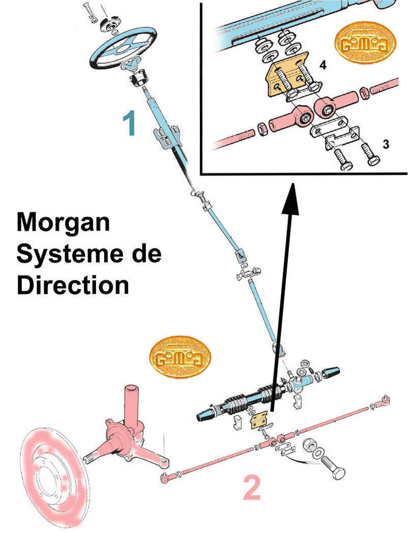
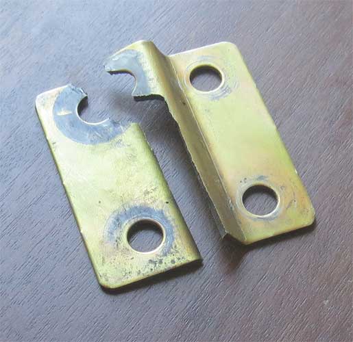 Examine the Jack Knight R&P steering
system to the right. The front wheel assemblies (tyres, wheels, brakes,
bearings, stub axles, tie rods (#2
shaded red) are all bolted (#3) by a single plate (#4
shaded brown) to the steering rack (#
1 shaded blue) , column and the steering wheel. On the Jack Knight cars (1984-2007)
it is part # MSR0287 and they call it the "steering rack mounting
bracket". On the Quaife R&P (2007 to present) it is part # H-2M1-05 which is identical, so the problem
seems to have been inherited from one steering system to another, unchanged in 35 years and counting. Sad stuff, but there you have it. Here are diagrams for the Quaife.
Examine the Jack Knight R&P steering
system to the right. The front wheel assemblies (tyres, wheels, brakes,
bearings, stub axles, tie rods (#2
shaded red) are all bolted (#3) by a single plate (#4
shaded brown) to the steering rack (#
1 shaded blue) , column and the steering wheel. On the Jack Knight cars (1984-2007)
it is part # MSR0287 and they call it the "steering rack mounting
bracket". On the Quaife R&P (2007 to present) it is part # H-2M1-05 which is identical, so the problem
seems to have been inherited from one steering system to another, unchanged in 35 years and counting. Sad stuff, but there you have it. Here are diagrams for the Quaife.
A
quick examination of the diagram shows that this little bent plate (an
in-house part) is the heart of the system's security and integrity. A. If
even one of the inner plate bolts break, the plate will only be held to the
rack by a single remaining bolt and the steering will be prejudiced. B. If
one of the outer bolts holding the tie rod ends, one wheel will not longer
be attached to the steering system. C. Happily the newer bolts are graded and held with
with lock tabs and nylocs. However, the plate itself has been known
to sheer along the fold lines without any prior indication. The result will most likely be horrific as one or both front wheels will detach from the steering system and splay outward. It
happened
to me at the end of one of the finest Morgan days I ever had! A
fantastic 780 mile drive and just as I was entering my
garage! I finished the trip with my wife and daughter at each of the
front wheels steering them by hand into my workshop. I do not recall
any extraordinary impact on that trip but I did notice the steering had
become sloppy in the last 30 miles (by that time the plate was likely
held together by bolt pressure only. However, it was night time by then
and I was close to home. That was a stupid mistake..only covered by
insanely
good luck! And I do NOT like relying on luck.
REDUX I was told once that my dear friend Button has mused publicly that something has to be amiss in this watchpoint.
Namely that my photos are suspect as he has never experienced this
phenomena with his r&p. Bill has never had an R&P. :) Button has offered this sort of
thing before with other of GoMoG watchpoints
that have saved people's lives. He does not do this with ANY malice and
I only wish dear Button was herel! The fact is that I do not
recall any event on that trip which was unusual to my 250,000 miles of
mogging on two continents (Europe and America). Of course, I had a road
clunk or two over the 1800 miles of back roads on that trip but nothing
out of the ordinary, and the state of my suspension is
legendary...(though achievable by anyone with a standard Morgan who
wishes to follow this manual.) In any event, this plate should
never fail NO MATTER WHAT the road anomaly. Of course, I have run
across this mishap with others since..and, as well, it must be
pointed out that dealers are always reluctant in this new era to get in
trouble with the Factory by going on the record. I cannot count the
times over the last 25 years, the more concientious Agents have
enlisted me to speak for them. Many of these warnings have now been
incorporated into Morgan lore and the production line.
This is time for remembering one of the most important GoMoG Laws.
| THE GOMOG LAW OF WARNINGS: As I taught my beloved chidlren (now adults), there
are warnings you can question and ignore because even if they occur they
can only cause annoyance. Then there are other warnings, if ignored, that can
cause dire tragedy with one incident. If there is no downside, always
believe and act upon the latter when it causes you no effort or cash
to respect. After all, what is the downside? Just adding the gussets is virtually costless. |
With the help of metal and mechanical experts and MMC dealers, I found out the cause. These plates likely break because they are improperly cold-bent and subsequently become vulnerable at the bend. When steel is cold
bent, its yield stress increases and its ductility decreases. Ductility
is a metal's ability to deform under tensile stress. Residual stresses,
enbrittlement, spring-back, reduction in toughness and curl are also common
problems of cold-bending metal. Cold bending can cause strain-aging. Dynamic
strain aging occurs during bending. But
whether hot or cold bent at Morgan, it sheared. And this is
not something that has to be brought my attention twice. There are
parts that can fail many times and merely cause annoyance. This is not
one of those. It must be addressed.
More importantly. Now I know
that these plates can break BEFORE any other part in the entire steering
assembly, belying the basic design principle that the most crucial part
in any assembly should be the one that fails last. On the other hand, as
it should be the last to fail, it can be strengthened to any degree without
effecting other parts or the Sequence of Failure.
MY SOLUTION:
Unlike so many of the Morgan aftermarket predators that have
appeared in the last decade, I favor simple bullet-proof
non-invasive solutions, in keeping with a 1930s (Golden Age of Automolbiling) technology car. 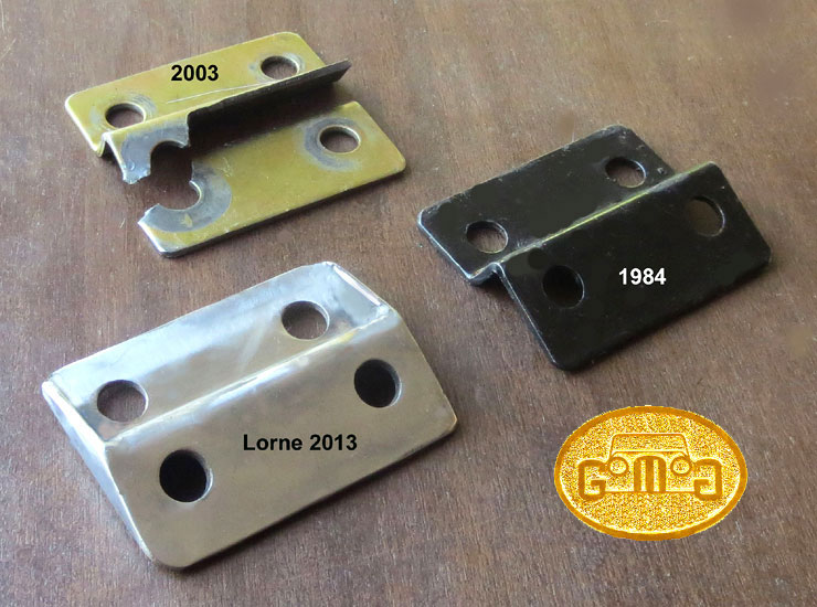 I
had an extra center plate left from an earlier R&P Morgan but I
intensely
dislike using a part that I know now is capable of failing,
disasterously. How many times does a disaster have to occur to be
tragic?!!!) So I designed
something more far more substantial and smarter and made it up. I replaced the
plate with a new center
I
had an extra center plate left from an earlier R&P Morgan but I
intensely
dislike using a part that I know now is capable of failing,
disasterously. How many times does a disaster have to occur to be
tragic?!!!) So I designed
something more far more substantial and smarter and made it up. I replaced the
plate with a new center 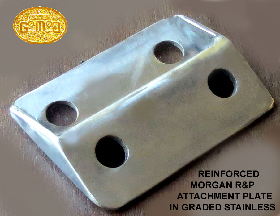 plate
using a stainless steel grade more capable of sustaining ANY possible stress or
impact that the steering assembly could possibly encounter or produce over time or wear. .
plate
using a stainless steel grade more capable of sustaining ANY possible stress or
impact that the steering assembly could possibly encounter or produce over time or wear. .
I
chose Type 304 stainless steel as it is rust
resistant, durable and far more likely to bend than shear like the
Morgan part. It is easy to make at home or small machine shop
fabrication. It is easy to clean. It can be polished to a mirror finish.
I
also increased the stock used to 4 mm rather than the 3 mm (1/8"?)
stock Morgan used for the original.
I also reinforced the plate I by welding on side gussets to reinforce the
bends and I heated the bends before shaping them. My end product is
MUCH stronger than
the MMC affair. I no longer worry about a reoccurence.
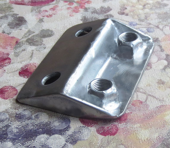
Lastly, I tapped the lower holes and welded graded stainless steel stoffer nuts at the rear of the holes. See Below. This is a foolproof way of preventing the plate from losing its bolts.
It is overbuilt, but that is what common sense dictates with any
component that is as life-important. That will eliminate the need
for lock tabs or wire on the lower bolts but I will still use Loctite
Red or Green. Please
note that even the smallest movement of the bolts within the plate bolt
holes can affect your wheel alignment. Please have checked them any time
your remove the plates or its bolts.
PART 2
This was added after the part of the article above brought the customary
wave of article feedback. It allowed some light to shine on why plate shearing
is rarer than one should have thought it would be. It showed that there
IS a possible spot that will fail before the plate and is likely inter-related.
The feedbackers, who had rushed to check their plates, did not notice anything
amiss with any. Of course, it would be only by very lucky coincidence
that someone would catch a plate before in the process of shearing. It
is a process that takes very little time from start to finish so there
is normally little if any warning. However, many souls have reported that
there was play at the steering wheel and/or they discovered their lower
bolts on the plate, those holding the tierods, had loosened significantly,
despite the lock tabs being installed properly. Here is an example.
Video
1
Video
2
The
sequence seems apparent. If the nylocs ARE capable of holding (with the
application of the right loctite or with lock tabs of their own)
then the entire stress is transferred to the plate itself, and, in some
cases, it shears. Neither event are happy results as the control of the
car is lost.
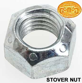 Stover
Self-Locking Nut Stover
Self-Locking Nut
 Stover Nuts are vibration
resistant self locking nuts. Stover Nuts are vibration
resistant self locking nuts.
Advantages:
1. The self locking function
of the Stover Nut is still effective after a number of applications, hence
it can be used many times.
2. The Stover Nut is an
all
metal Stiff Nut (available in graded metal).
3. It is resistant to shocks,
vibration and dynamic loads.
4. The locking function
of the Stover nut is achieved by the deformation of part of the nut and
it does not rely on nylon.
5. It has a much lower profile
than nylocs or regular nuts with lock washers.
I use stoffer nuts to replace
the untorquable nylocs the MMC use in critical areas. These include the axle u-bolts
(where proper axle nuts cannot be be used for clearance reasons and the
nylocs loosen as a sad tradition. I also use them at the propshaft.
N.B. A stoffer nut will run smoothly
until it reaches the deformed part after which the clamping force will
subsequently increase and require effort to thread.
|
|
SEQUENCE
of FAILURE: All
moving parts fail..eventually. So ideally, parts in any assembly (and each
individual assembly itself) should be designed and made to fail in a specific
sequence, with the most critical parts failing last. In this way, safety
is enhanced and damage pre-controlled. That is why we are so often instructed
to replace many parts in an assembly when one fails. In doing so,
we are trying to preserve the proper sequence of failure.
However, amateur (and often
"professional" mechanical designers will often replace a failed part with
something much stronger they have made themselves. Without careful examination
and understanding, that replacement can change the sequence of failure
and increase the risk of much greater damage.
|
Bump
Steer
by Lorne Goldman
I
imagine this bit will also cause protests in some corners. I acknowledge that there have been many
who have written sagely and with great solemnity on this subject. They
have pondered for decades on such sundries as to whether the tie-rods
should be afixed atop or below the stub axle arms, or how much longer
the rods should be to minimize bump steer.I am sorry for them for this bit. Indeed, many in the new predatory
aftermarket have convinced owners to spend silly sums of money and
effort curing it. Even the older significantly more honest aftermarket will sell cures (much less
expensive) to those that have been convinced
to fret about it. But they confide to me that their cures are out of
kindness and a recognition of the psychological relief they provide.
(wry smile)
However, the truth
of the matter is that the famous flexing of the Morgan chassis makes
bump steer unimportant..a non-issue..or at least impossible to deal with aside from car by car.
Whenever
they-who-wish-to-apply-other-automotive-technology consider the
Morgan suspension
and steering, they omit to factor in the impossible-to-quantify, namely
the flexing of the chassis.
This flexing not only varies from chassis
to chassis, car to car, it also changes with each model and each car
over time/usage. Measures that are designed for one car will not help
another except by coincidence. It may even cause a prejudice.
Imagine designing something for an old well-used 4/4 and
transferring it to a later heavier Plus 8 or Roadster!! However,
the newer "experts", are reluctant to admit or even acknowledge
the most salient and influential component on the car. The chassis and
the open top which have to individualize every car. But individual cars
cannoit generate one-size-fits-all profits...so the convince the market
that all Morgans are identical.c They
plunge
ahead, trained and limited by an education and training that applies
to the type of chassis
of other vehicles use.
Indeed, sometimes their kit will be an improvement to a varying degree
from car to car, sometimes it will add nothing and just as often it
will prejudice the suspension.
It
is for you to decide, for yourself, whether you think all Classic
Morgans are a bit different or identical. Ask THAT question of your
peer group! Sadly, these things have become "poltical" rather than
decided by common sense. Too little savvy and too much money.
:(
There
is a wonderful Peter Morgan anecdote that is germane. Some 70 years ago
he fit shocks to the Morgan front, fit alongside the kingpin springs,
just as they are today unchanged since then. When asked whether
they improved the handling or the ride, PM shrugged, indicating they
had no effect that he could discern. But he confided that buyers were
concerned as they saw them on other, different cars..so he slapped
them on. ;)
One day, for your own amusement and in memory of Peter Morgan, remove your front dampers and go for a test drive.