Making New Panel Pieces
by John Blair
The sill plates were surprisingly easy to make but require access to several expensive machines. When the car was totaled, I had purchased a new sill plate but didn't use it. Consequently, I had a good template to work from. Since both sides are mirror images of each other, the one template could be used to layout the two new pieces. I purchased a piece of 1 inch thick oak and ran it through a planner to get it down to required 3/4 of an inch thick. Next I set the template on the board and traced 2 sill plates. I used a band saw to cut the sill plates to the approximate size. Then I clamped the original sill plate to one of the rough blanks and used a 1" belt/disk sander to sand off the excess wood. The little curve, near the back of the sill plate, was smoothed with a drum sander chucked up in a drill press. The hard cut was the curve, in the side of the sill plate, where the fender fits. To make this, I clamped the original sill plate to the new one, then marked off several lines across the thickness of the boards. Next using a pair of dividers, I measured the thickness of the original at each of the lines and transferred this to the new piece. The curve was sketched by connecting all the marks. The cut was made using a vertical milling machine. (It could have been made using a table saw, but it would have been harder, as a spacer would have to be made.) The same process was used to make the 2nd sill plate. Once the new pieces were finished, they were coated with epoxy, sanded, re-coated with epoxy, and re-sanded.
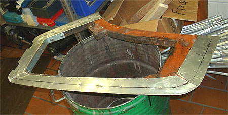
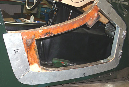
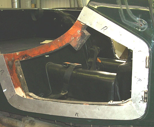
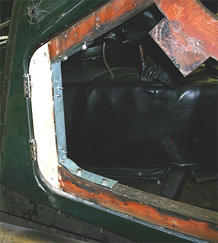
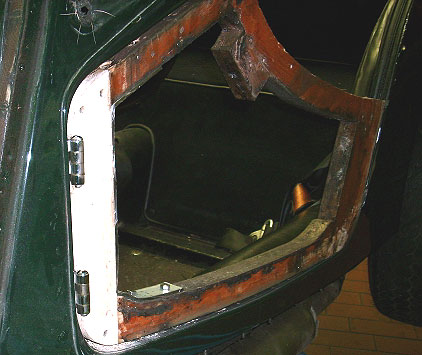
The right fender arch had lost the back 2 inches or so due to wood rot. The front lip, where it bolts to the sill plate, also had rotted, and the inner panel had to be replaced. The new inner panel was made by tracing the outline of the old panel on a piece of 1/2" BCX plywood and cutout using a saber saw. (The original panel was 3/8 inch plywood. I had intended keeping it stock. Somehow I just blew it. However, after getting the new panel made, I decided that the extra 1/8 inch would not make that much difference - I hope!) The final shaping was done using the belt/disk sander. Using the transfer punch set, I marked and drilled all the holes. Next, 2 coats of epoxy were applied and sanded. To repair the arch, I started in the back about 2 inches forward of the rot and drew a diagonal line (about 4 inches long) across the arch. (This would give more surface area for the patch to mate to.) The rotted section was cut off using a band saw. I bolted the side panel back on so the angle between the panel and the fender arch could be measured using a protractor on a ruler (similar to a combination square). Once the angle was drawn on a 3/4" piece of oak, it was set on the fender arch and arch lines were extended using a yardstick. The patch piece was cut using a band saw. Next, the fit was checked by setting it in place. The final shaping was done using the belt/disc sander. When a good fit was achieved, the patch was clamped to the arch and 2 holes drilled so the patch could be screwed to the arch. Everything was disassembled again and epoxy was applied to both the patch and the arch, and the patch was re-screwed to the arch. The entire arch was coated with 2 coats of epoxy. The front lip was rebuilt using epoxy and a filler to thicken it. I placed masking tape around what was left of the lip, to form a dam, and applied the thickened epoxy to the damaged area.
I finally decided to tackle the doors. After I removed the interior panels, I couldn't figure how to remove the door skin from the wooden frame. I finally decided to call John Sheally again and ask how the doors were built. He said "the wood door frame is assembled and a metal flange is nailed to it. Then the door skin is set on and the edges of the skin are crimped over the metal flange." He suggested not trying to disassemble the doors. I will have to sand the wood and the inside of the door. (I don't suggest using any paint stripper, and if it gets under the wood it would be difficult to neutralize.) After cleaning the inside of the door and the wood, I will apply epoxy to the wood and repaint the metal. The factory makes the door inner panels using 1/8" plywood which has disintegrated. I made the replacement panels from 1/4" plywood sealed with epoxy and will cover it with 1/4" foam rubber and naugahide.
The firewall attaches to the front of the wood sub frame. This wood is composed of 3 separate pieces with a small piece of plywood inserted between each vertical piece and the horizontal piece. I cleaned up the slots with a milling machine. However, they could have been cleaned with a table saw. To make the braces, I inserted a piece of poster board into each slot and traced the outside of the wood. I cut out the template and traced it on to some scrap 1/4 inch plywood and cut them out using band saw. The final shaping was done using the 1" belt/disc sander.
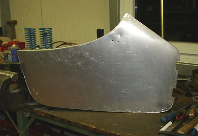
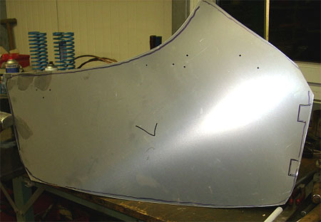
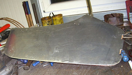
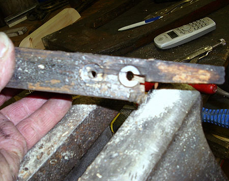
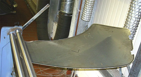
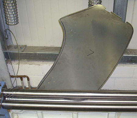
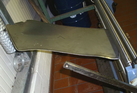
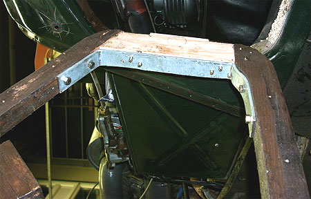
The last piece, to be made were the 2 curved pieces that support the sheet metal rear deck and fit on the outer edge of the fender arch just behind the cross brace. To get the curve, I used a curve tracing tool (made up of a lot of little rods held together by a cross brace). I placed this on the fender arch and tapped the top to get a nice fit. This curve was then traced on a small block of wood. The height of the cross brace was measured and transferred to the block of wood and the upper curve was sketched freehand. I used a band saw to cut the part out. Final shaping and smoothing was done using a drum sander chucked up in a drill press.
Fasteners for wood
sub frame
by John Blair
Item              Description                                     Total # required

1.    #8 x 3/4" Flathead wood screw
         a) 6   b) 8   c) 4   d) 6                                        24

2.    #8 x 7/8" round head wood screws                     25

3.    #8 x 1" Flathead wood screws
         a) 4   b) 8   c) 2                                                 14

4.    #8 x 1 1/4" Flathead wood screws
         a) 2   b) 4   c) 6   d) 2                                        14

5.    #8 x 1 1/2" Flathead wood screws
         a) 2  b) 4                                                            6

6.    #8 x 1 3/4" Flathead wood screws
         a) 0   b) 6   c) 4                                                 10

7.    #10 x 1" Flathead wood screws
          a) 8   b) 4   c) 2   d) 0  e) 4   f) 28  g) 8             54

8.    #10 x 1 1/4" Flathead wood screws
          a) 6                                                                    6

9.    #10 x 1 1/2" Flathead wood screws
          a) 6                                                                    6

10.   #10 x 2" Flathead wood screws
          a) 4  b) 4                                                            8

11.   #8 x 2 1/4" Flathead wood screws
         a) 4                                                                     4

12.   1/4 x 2" carriage bolts
          a)  4 - used to hold the trunk frame to the rear fender wells
          b)  4 - used to hold the rear tire support frame to the rear
                  fender wells
          c) 10 - used to hold the wooden frame to the chassis
Notes: 1. Since both sided of the car are mirror images, each numbered |