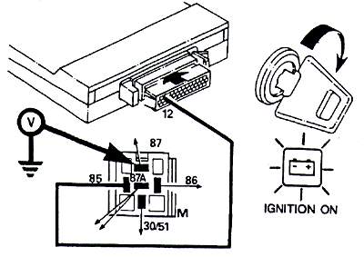
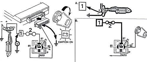
| 1. Check voltage from batterie to the ECU | On the multimeter the battery voltage must show. (minimum 10V) |
 |
|
| Possible fault: Check earth |
In case of differing measurements first inspect the wiring drawn in bold lines
| 1. Check voltage from batterie to the ECU | On the multimeter the battery voltage must show. (minimum 10V) |
|
|
| Possible fault: Check earth |
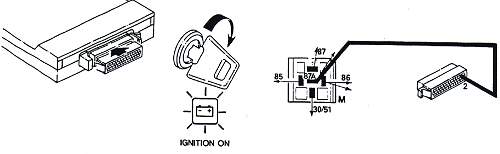
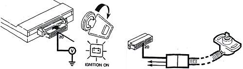
| 2. Check voltage from ignition to the ECU | On the multimeter the battery voltage must show. |
 |
|
| Possible fault: Check earth |
| 3. Verify if main relay works - first step | |
 |
Multimeter must show battery voltage. If 0 Volt see next step |
| 4. Verify if main relay works - second step | |
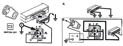 |
A = must be battery voltage, if OK ECU possibly faulty, B = must be 0 Volts when ignition off |
| 5. Verify if pump relay works | |
 If the relay is OK go to 6 |
Listen to a "click" from the pump relay |
| 6. Verify pump relay circuits | |
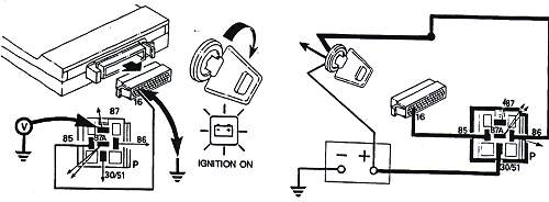 |
Pin 87 must show battery voltage if other conditions fullfilled. If so, the ECU is suspect. |
| 7. Check if fuel pump gets current | |
 |
If the pump is the in-tank model with connectors on the upper side of the tank- and inaccessible. However there is a connector not far away up the wiring harness where you can check voltage. |
| 8. Check engine rpm signal and resistance | |
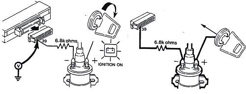 |
Check if Pin 39 has battery voltage on the multimeter. Check resistance between coil and Pin 39 (6,8 kohms) |
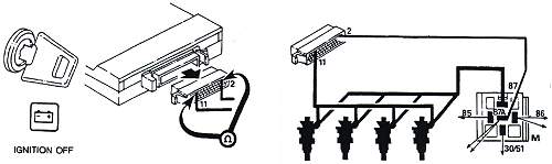
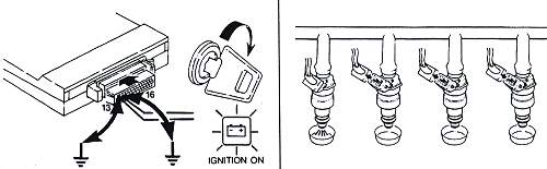
| 9. Check injectors (Pin 13 is for injectors 1,3,5,7) | |
|
Reading of 5-6 ohms=1 injector suspect Reading of 8-9 ohms=2 injectors suspect Reading of 16-17 ohms=3 injectors suspect Reading of more=get your gun and shot it! |
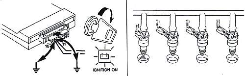
| 10. Check injectors (Pin 11 is for injectors 1,3,5,7) | |
 |
Connect ohmmetre between Pin 2 and 11. Reading of 4-5 ohms is OK. |
|
Reading of 5-6 ohms=1 injector suspect Reading of 8-9 ohms=2 injectors suspect Reading of 16-17 ohms=3 injectors suspect Reading of more=get your hammer and give it a good tap! |
| 11. Fuel temperature sensor | |||
 NB: If your fuel temperature is over 80°C or 176°F - let all go and run! That thing will blow any moment |
°C |
°F |
Correct read in ohms. |
|
-10° 0° 20° 40° 60° 80° 100° |
14° 32° 68° 104° 140° 176° 212° |
9100-9300 5700-5900 2400-2600 1100-1300 500-700 300-500 150-200 |
|
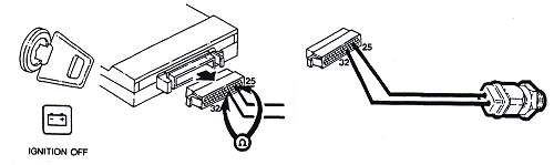
| 12. Coolant sensor check | |||
 |
Connect ohmmetre between Pin 25 and 7. | ||
| °C | °F | Correct read in ohms. | |
|
-10° 0° 20° 40° 60° 80° 100° |
14° 32° 68° 104° 140° 176° 212° |
9100-9300 5700-5900 2400-2600 1100-1300 500-700 300-500 150-200 |
|
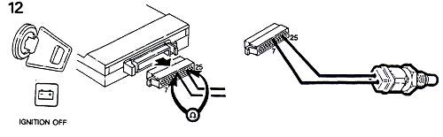
| 13. Verify air bypass valve | |
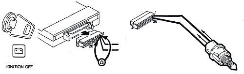 |
Connect multimeter between Pin 26 and 1. Correct reading: 48-58 ohms. If not verify wiring |
| 14. Verify air bypass valve - second part | |
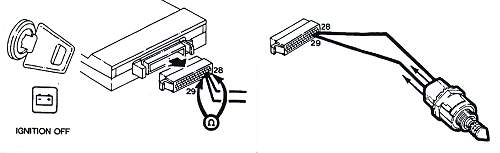 |
Connect multimeter between Pin 28 and 29. Correct reading: 48-58 ohms. If not verify wiring |
| 15. Check throttle potentiometer | |
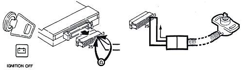 |
Connect multimeter between Pin 25 and 3. Correct: 5000 ohms, if different go to next step |
| 16. Check throttle potentiometer - second part | |
 |
Connect multimeter between Pin 20 and ground Throttle closed: 0,29V-0,36V Throttle open 4.6V-5,0V Important: Voltage must grow linear when moving flap and must not jump |
| 17. Check Hot Wire Mass Airflow Sensor | |
 |
Connect multimeter between Pin 35 and ground Correct: 0,3V-0,6V |
The following steps must be taken with some precautions. The fuel system must be depressurised as pressure stays inside the lines and a dangerous spray will occur when you open them. Also the slightest dirt particle in the system upstream of the filter (nearer to the engine) will definitely deteriorate the system. Some spilling can't be avoided, so take care.
| 18. Fuel Pressure check | |
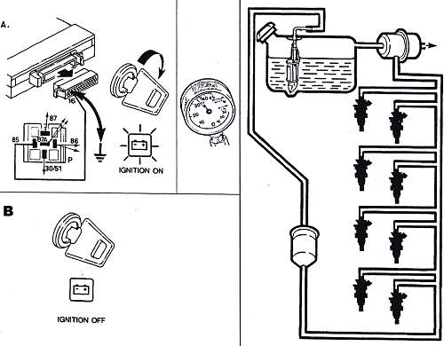 |
Correct reading: 2,4-2,6 kg/cm2 or 34,0-37,0 psi AND a pressure drop of not more than 0,7 kg/cm2 or 10 psi in one minute. |
| 19. Injector leak test | |
 |
Injectors may leak. Take all the injectors out but don't disconnect them from the fuel rail. Put some sort of receptable under them and switch on ignition. Any injector that gives off more than 2 drops a minute must be replaced. If you have to replace a leaky injector you must inspect the spark plugs for fouling! |
Take care: The following steps are more dangerous as the spray can ignite quite easily
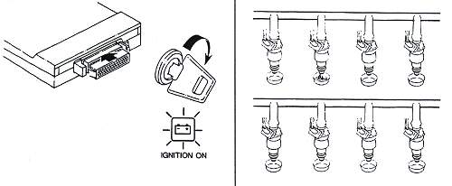
| 20. Injector flow test (left bank, 1,3,5,7) | |
 |
Ground Pin 13 and 16. This will cause the injectors to open. Place a large receptable under the injector, maybe a bottle or so. A correct injector will flow 167 cm3 per minute! |
| 21. Injector flow test (right bank, 2,4,6,8) | |
 |
Ground Pin 11 and 16. This will cause the injectors to open. Place a large receptable under the injector, maybe a bottle or so. A correct injector will flow 167 cm3 per minute! |
| 22. Gear input switch (Inhibitor switch) (automatic trans only) | |
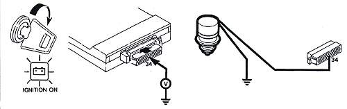 |
Connect multimeter between Pin 34 and ground Correct reading: 0V in Park and Neutral 4,5V-5,0V in R, D, 3, 2, 1 |
| 23. Road speed input (Speed Transducer) | |
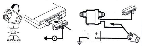 |
Jack up and slowly turn left rear wheel. Connect multimeter between Pin 6 and ground. Correct reading: 0-12V, changing 6 times per revolution of the wheel |
| 24. Check Lambda sensors | |
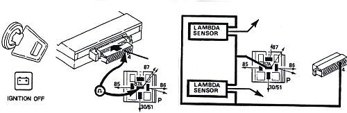 |
Take out the fuel pump relay Connect multimeter between Pin 4 and 87A of the fuel pump relay socket. Correct reading 2,65-3,35 ohms A reading between 5,3 and 6,7 ohms indicates one of the 2 Lambda sensors is shot |