


 I can place the relays in the right wires anywhere between the stalk and
the headlamps. It might as well be the most convenient placement. The
wires split from two to four at the fusebox so between the stalk and the fusebox is easiest. The stalk used (1977-1997)
helps as its loom is very long. So I chose to place the relays right under
the dash not far from the stalk. Your target wires are Blue with a Red
tracer and Blue with a white tracer. Unravel the tape on the stalk loom and
you will find them.
I can place the relays in the right wires anywhere between the stalk and
the headlamps. It might as well be the most convenient placement. The
wires split from two to four at the fusebox so between the stalk and the fusebox is easiest. The stalk used (1977-1997)
helps as its loom is very long. So I chose to place the relays right under
the dash not far from the stalk. Your target wires are Blue with a Red
tracer and Blue with a white tracer. Unravel the tape on the stalk loom and
you will find them.
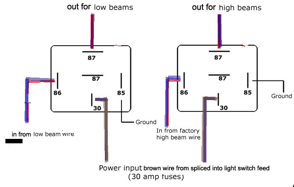
Onto the wiring. You will have to bear with me on this. When I do something to my Morgan, I spend the extra time to do so in a fashion that I can easily reverse it..especially when I wire something into an existing system. That will produce a little more work here but will leave you capable of moving everything to the original wiring in a minute.
Let's start with the relays. There are many types of relays. In this case,
the world has made life simple for us. You need what the auto stores sells
as "headlamp" relays. (smile) Two of them. They look like standard little
black plastic box relays. Now make some little looms. This will be dictated
by what you have and what you need.
1. Each relay will require battery power to the blade labeled 30 amp on
the relays. Make a loom. It will take the battery power that is already connected
intI place
mine so I can easily access it from the passengers seats. I have no
patience with the installation in the engine bay. By the time you get
there you have stalled in a place you may not enjoy. I can get my car
going before the car stalls after that one time a year I hit a bad
bump. o to your light switch. (The bigger brown wire.) This loom will have a
four wires, a male connector going in three wires with females connectors.
(I solder the junction and shrink cover it.) Th male connector will be fitted
to the pre-existing power wire into the main light switch. One of the females
will go back on the main light switch. The other females will go into the
30 amp position on each relay.
N.B. Make sure that your male and female connectors match up.
2. Now make another little loom of three as robust wires. A circlet connector
with an id suitable to the bolt you have chosen for a ground/earth source.
The ends of the other two wires will be fitted with females connectors.
Attach these to the ground entry on the relays.
3. Now to the wires from the stalk. Create sufficient unravel enough tape
to free wire on the blue/red and blue/white sufficient to easily to reach
the place you are going to fit or tie warp your relays nearby Cut the wires
at this point. Strip each side and place a female connector on one side and
a male connector on the other. Connect the female sides to position 86 on
the relays. Make two more little looms. Simply use two wires with female
connectors at both ends. Attach one end of each the the male connector
you laced on the original loom wire and the other end into position
87 on the corresponding relay. Voila! If I understand it correctly, the impacts
of headlights on off or dim dipping now do not reach the stalk. If
you want to get fancy, you can place an inline 5 amp fuse in the blue
wire (no tracer) that goes into the stalk. If you want to switch (pun!)
back, the use and placement of the female and male connectors will make that
a simple plug and play.
For the more ambitious amongst us, here are some pictures I found on the net a few years ago that can result in a repair. This switch is from a UK 1973 model.
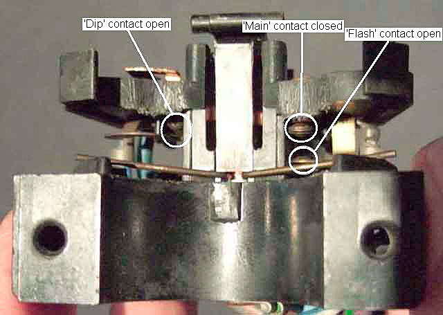
| Showing the switch in the 'main beam' position, 'dip' and 'flash' contacts both open. |
|
|
|
Showing the switch in the 'dip beam' position, 'main' and 'flash' contacts open. |
| Showing the switch in the 'flash' position, dipped beam contact still closed (but the spring contact pushed further than before) 'main' contact still open. |
|
|
|
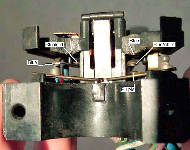
Showing the switch in the 'dip beam' position with the contacts labelled as to which colour wire goes where. |
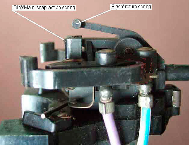
| A general view showing the plastic springs (and indicator/turn-signal auto-cancel fingers) on the switch body. The 'Dip'/'Main' snap-action spring gives the positive switching action between dip and main positions. The 'Flash' spring gives a positive return to 'Dip' from 'Flash'. |
|
|
|
Switch in the 'main beam' position, the flasher return spring clear of the switch body. |
| Switch in the 'dipped beam' position, the flasher return spring just touching the switch body. |
|
|
|
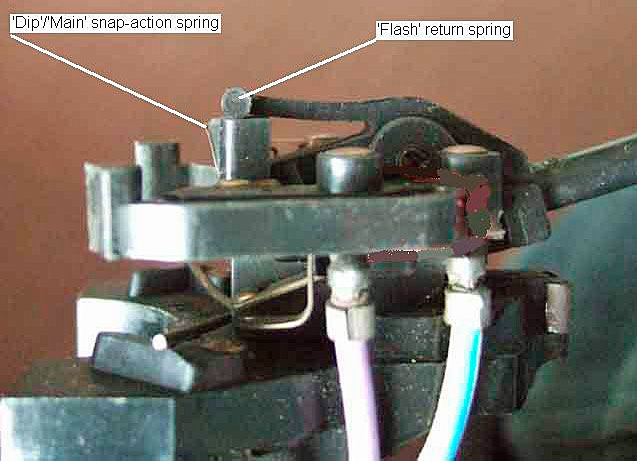
Switch in the 'flash' position, the flasher return and dip/main snap-action springs under tension. |
 by Lorne Goldman