Andover, CT
Formatted by: John T. Blair (WA4OHZ)
Originally Written: February 2002
Last updated: June 18, 2009 - Reformatted & corrected my email address
| I decided to move the dip switch from above the clutch pedal to the dash. This lets me change from Hi to Low easily and to flash my headlights. The idea of not having the headlight current pass through the light switch also seemed like a good one. My '61 Morgan has toggle switches to control the wipers, the instrument lights turn signals and the driving light, but this circuit will work on any car, and is easily accomplished with 2 "Bosch" 30 amp single pole double throw relays (ED: I purchased an equivalent relay from the auto parts store, a Sorensen MR 38 for $12.99 and another one from Radio Shack, part #2750226, for $6), a double throw toggle switch some wire and a few spade lugs. Because I wanted to make the modification almost invisible I used a cream turn signal switch which I purchased from Melvyn Rutter. | 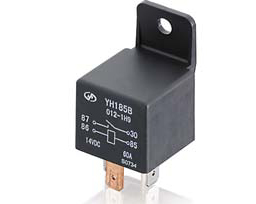 Bosh Style Relay |
On my dash the wiper switch is next to the steering wheel, then the inspection sockets, then the switch for the driving light then the instrument light switch. The driving light has been missing for almost 30 years. Not wanting to add any additional holes in the dash, I moved the wiper switch to the driving light switch location. A double throw turn signal switch was installed vertically in the former wiper switch location. Up is "High", center is "Low", and down is "High Flash. The light switch turns the low beams on by applying power to the coil of relay K1. When energized, K1 will supply power to the low beams through its normally opened contacts and the normally closed contacts of K2. All of the headlamp current now will flow through the relays. The light switch only supplies current to the relay coils and to the parking lights and the rear lights. (ED. This is a good thing as it reduces the current in the Headlight switch - a very expensive item, and this should increase its life expectancy.) The Flash current is through the Flash Switch and the normally open contacts of K-2.
I mounted the 2 relays on a piece of aluminum that is bolted to the back side of the original foot operated dip switch, on the engine side of the fire wall. Disconnect the Ground terminal from the battery before starting working on the wiring. Temporally identify the relays as K-1 & K-2. Do not mount the relay panel yet. There are 3 spade connectors with 6 wires to be removed from the old dip switch and pulled through the fire wall. You can then remove the old dip switch or leave it in place.
The wire colors on the wiring diagram follow Lucas practice, the colors of the new wires are an attempt to maintain the color coding, The circled numbers on the wiring diagram correspond to the steps below. The terminal numbers on the new dip switch are the Lucas numbers on the switch.
1) A new Blue wire was run from a convent source of +12V, I chose terminal A-1 on the control box (ED. voltage regulator), to K-1/30. This was run from from terminal A-1, along the inside of the fire wall, and out the hole above the old dip switch.
2) The Blue wire that was removed from the old dip switch now connects to, K-1/86.
3) A new wire is run from K-1 /87 to K-2/30.
4) Then K-1 /85 connects to K-2/85 and to a good ground.
5) At the light switch terminal 4 add a Blue wire to term 7, the wiper, of the new dip switch.
6) Run a new Blue/White wire from term 8 of the new dip switch to K-2/87 and crimp to the Blue/White wires (2) that were removed from the old dip switch, this goes to the head lamps high beams.
7) Under the dash remove the Blue/White wire from the high beam warning light, cut the lug off and crimp a short Blue/White jumper. Replace the lug on term 8, the Flash terminal of the new dip switch. Attach the jumper to the warning lamp.
8) Connect the remaining Blue Red wires (2) from the old dip switch to K-2/87A, this goes to the low beams.
9) If you feel more comfortable having the light circuits fused add a fuse block and 2 fuses , one for the high and one for the low beams. Don't do steps 6 and 8. Connect the Blue/White wires from the old dip switch to the load side of one of the fuses and the Blue/Red to the other fuse. Step 6a). Run a new Blue/White wire from term 8 of the new dip switch to K-2/87 and to the Blue/White fuse.
Step 9a)Run a Blue/Red jumper from K-2/87A to the Blue/Red fuse.
A 10 Amp slow blow fuse is a good size.
Connect battery and try the new switch. The Light Switch now turns the low beams on with dip switch center off. Pushing the dip switch down will add the high beams to the low beams. (What this circuit will do is allow is to flash the hi beams while keeping the low beams on. It is a VW thing, and is especially useful for lighting up street signs, dark turns, and getting an oncoming drivers attention.) Switch up will turn on the high beams and turn off the low.
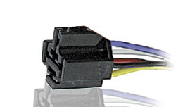 Relay Socket /w pigtails |
(ED - June 2009 - One additional note. If you are planning on doing such a mod I
suggest that you get a socket with pigtails for the relay. It makes putting the
system together and maintaining it a lot easier. The parts can be purchased at your
local Radio Shack or mail ordered from Allelectronics.com. Allelectronics part numbers are: Relay - RLY-351 - about $2.50 Socket - SRLY-2 - about $2.00) |
To view the wiring diagram
To print the wiring diagram - (This
will rotate the diag 90deg. then select "file" and
"print")
Return to the Index of Tech. articles
To email the webmaster with comments or questions.